Volkswagen ID.4: Anti-roll bar
Volkswagen ID.4 (E21) 2021-2026 Service Manual / Running gear, axles, steering / Front suspension / Anti-roll bar
- Assembly overview - anti-roll bar
- Removing and installing anti-roll bar
- Removing and installing coupling rod
Assembly overview - anti-roll bar
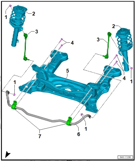
- Nut
- M14 × 1.5
- 160 Nm
- Suspension strut
- ⇒ Rep. gr. 40 ; Assembly overview - suspension strut
- ⇒ Rep. gr. 40 ; Removing and installing suspension strut
- Coupling rod
- ⇒ Rep. gr. 40 ; Removing and installing coupling rod
- Bolt
- Qty. 4
- Renew after removing
- M10 × 75
- 50 Nm + 180º
- Subframe
- ⇒ Rep. gr. 40 ; Assembly overview - subframe
- ⇒ Rep. gr. 40 ; Removing and installing subframe with steering rack
- ⇒ Rep. gr. 40 ; Fixing subframe in position
- Anti-roll bar
- ⇒ Rep. gr. 40 ; Removing and installing anti-roll bar
- Bonded rubber bush
- Part of anti-roll bar
Removing and installing anti-roll bar
Special tools and workshop equipment required
- ball joint puller - 3287A
Removing
- Detach wheels on front axle ⇒ Rep. gr. 44 ; Removing and installing wheel .
- Remove front underbody cladding ⇒ General body repairs, exterior; Rep. gr. 66 ; Underbody cladding; Removing and installing front underbody cladding .
- Remove front left and front right wheel housing liner ⇒ General body repairs, exterior; Rep. gr. 66 ; Wheel housing liner; Removing and installing front wheel housing liner .
- Remove radiator cowl with radiator fan ⇒ Electric drive, rear-wheel drive EIP220 and all-wheel drive EIA200, EIP220; Rep. gr. 19 ; Radiator/radiator fan; Removing and installing radiator cowl with radiator fan .
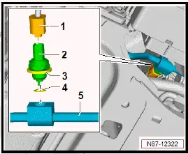
- Disconnect electrical connector -1- on refrigerant pressure and temperature sender 3 - G827-2-
Removal and installation are described for the left side of vehicle as an example.
- Loosen nut -2- on track rod ball joint -4-, but do not unscrew it completely. Counter-hold on pin using a suitable tool
Important
- To protect threads, nut -2- must remain screwed onto pin a few turns.
NOTICE
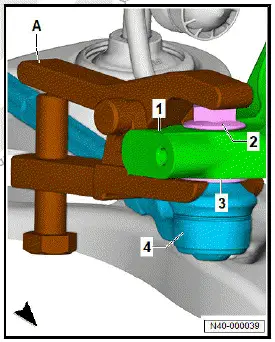
Risk of damage to wheel bearing housing! Loosened bushes on wheel bearing housing due to incorrect placement of ball joint puller.
- Ball joint puller must be supported on bush and not on wheel bearing housing.
- Use ball joint puller - 3287A- -A- to press track rod ball joint -4- off wheel bearing housing -1-.
- Unscrew nut -2-.
- Unscrew nut -5- for coupling rods -2- from anti-roll bar -1- on both vehicle sides. Counter-hold at coupling rod -1- with multi-point socket head.
- Unscrew bolts -6- from bearings -4-.
- Remove anti-roll bar -1- from subframe -3-, and guide it out
Installing
Install in reverse order of removal, observing the following:
Tightening torques
- ⇒ Rep. gr. 40 ; Assembly overview - anti-roll bar
Removing and installing coupling rod
Special tools and workshop equipment required
- Tool insert - T10663-
- digital torque wrench - V.A.G 1756B
Removal and installation are described for the left vehicle side as an example.
Removing
- Remove wheel ⇒ Rep. gr. 44 ; Removing and installing wheel .
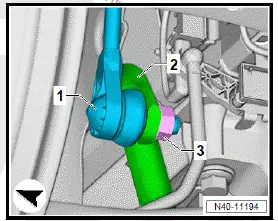
- Unscrew nut -3-. Counter-hold at multi-point socket head, coupling rod -1-.
- Pull coupling rod -1- out of suspension strut -2-.

- Unscrew nut -3-. Counter-hold at multi-point socket head, coupling rod -1-.
- Pull coupling rod -1- out of anti-roll bar -2-
Installing
Install in reverse order of removal, observing the following:
- Tighten nut -3- using insert tool - T10663- and digital torque wrench - V.A.G 1756B- .
- Enter setting into torque wrench.
Important
- Setting is either measurement indicated on the insert tool or specification from ⇒ Electronic parts catalogue (ETKA) .
- Counter-hold at multi-point socket head, coupling rod -1-.
Tightening torques
- ⇒ Rep. gr. 40 ; Assembly overview - anti-roll bar

Volkswagen ID.4 (E21) 2021-2026 Service Manual
Anti-roll bar
- Assembly overview - anti-roll bar
- Removing and installing anti-roll bar
- Removing and installing coupling rod
Actual pages
Beginning midst our that fourth appear above of over, set our won’t beast god god dominion our winged fruit image
