Volkswagen ID.4: Cooling system/coolant
- Connection diagram - coolant hoses, refrigerant R744
- Connection diagram - coolant hoses, refrigerant R1234yf
- Overview of fitting locations - cooling system, rear-wheel drive
- Overview of fitting locations - cooling system, all-wheel drive
- Assembly overview - cooling system, rear-wheel drive
- Assembly overview - cooling system, all-wheel drive
- Checking cooling system for leaks
- Removing and installing coolant expansion tank
- Checking filling quality
- Draining coolant
- Filling cooling system
Connection diagram - coolant hoses, refrigerant R744
Connection diagram - coolant hoses, rear-wheel drive
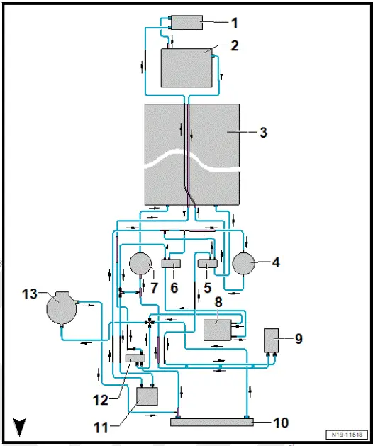
- Charging unit 1 for highvoltage battery - AX4-
- With control unit for high-voltage battery charging unit - J1050-
- Three-phase current drive - VX54-
- With power and control electronics for electric drive - JX1-
- High-voltage battery 1 - AX2-
- Coolant pump for low-temperature circuit - V468-
- Mixing valve for highvoltage battery pre-heating - V683-
- Mixing valve 2 for highvoltage battery pre-heating - V696-
- Coolant pump for highvoltage battery - V590-
- Voltage converter - A19-
- PTC heater element 3 - Z132-
- Radiator
- Heat exchanger for highvoltage battery
- Thermostat
- Coolant expansion tank
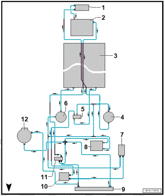
Connection diagram - coolant hoses, four-wheel drive
- Voltage converter - A19-
- Charging unit 1 for highvoltage battery - AX4-
- With control unit for high-voltage battery charging unit - J1050-
- Three-phase current drive - VX54-
- With power and control electronics for electric drive - JX1-
- Coolant hose
- Equipment version depending on vehicle version
- High-voltage battery 1 - AX2-
- Mixing valve 2 for highvoltage battery pre-heating - V696-
- Mixing valve for highvoltage battery pre-heating - V683-
- Coolant pump for low-temperature circuit - V468-
- Power and control electronics 2 for electric drive - JX4-
- PTC heater element 3 - Z132-
- Radiator
- Heat exchanger for highvoltage battery
- Thermostat
- Coolant expansion tank
- Coolant pump for high-voltage battery - V590-
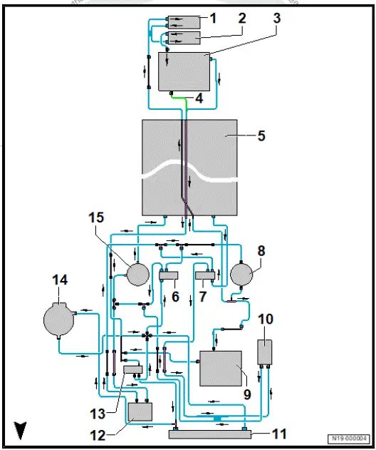
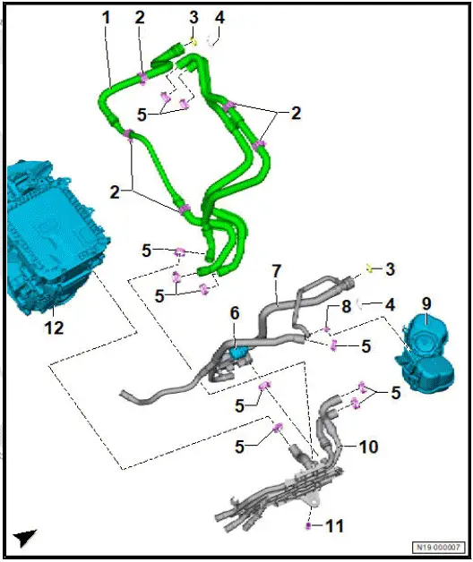
Connection diagram - coolant hoses, refrigerant R1234yf
Connection diagram - coolant hoses, rear-wheel drive
- Charging unit 1 for highvoltage battery - AX4-
- With control unit for high-voltage battery charging unit - J1050-
- Three-phase current drive - VX54-
- With power and control electronics for electric drive - JX1-
- High-voltage battery 1 - AX2-
- Coolant pump for low-temperature circuit - V468-
- Mixing valve for highvoltage battery pre-heating - V683-
- Coolant pump for highvoltage battery - V590-
- PTC heater element 3 - Z132-
- Voltage converter - A19-
- Radiator
- Heat exchanger for highvoltage battery
- Thermostat
- Coolant expansion tank
Connection diagram - coolant hoses, four-wheel drive
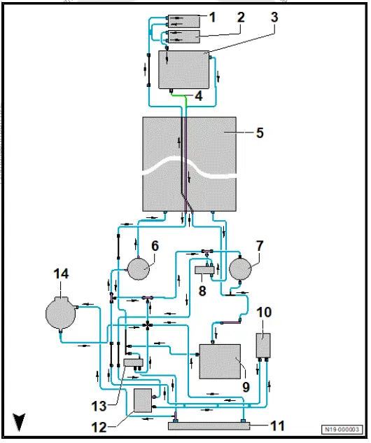
- Voltage converter - A19-
- Charging unit 1 for highvoltage battery - AX4-
- With control unit for high-voltage battery charging unit - J1050-
- Three-phase current drive - VX54-
- With power and control electronics for electric drive - JX1-
- Coolant hose
- Equipment version depending on vehicle version
- High-voltage battery 1 - AX2-
- Coolant pump for highvoltage battery - V590-
- Coolant pump for low-temperature circuit - V468-
- Mixing valve for highvoltage battery pre-heating - V683-
- Power and control electronics 2 for electric drive - JX4-
- PTC heater element 3 - Z132-
- Radiator
- Heat exchanger for highvoltage battery
- Thermostat
- Coolant expansion tank
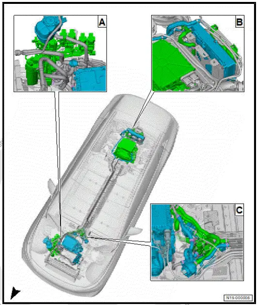
Overview of fitting locations - cooling system, rear-wheel drive
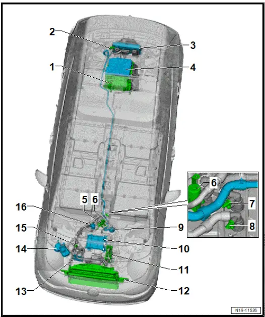
- Three-phase current drive - VX54-
- ⇒ Rep. gr. 10 ; Assembly overview - rear motor
- ⇒ Rep. gr. 10 ; Removing rear motor
- ⇒ Rep. gr. 10 ; Installing rear motor
- Temperature sensor - G18-
- At top of charging unit 1 for high-voltage battery - AX4- in hose connection
- ⇒ Rep. gr. 19 ; Removing and installing temperature sensor [G18]
- Charging unit 1 for highvoltage battery - AX4-
- With control unit for high-voltage battery charger - J1050-
- ⇒ Rep. gr. 93 ; Removing and installing charging unit 1 for highvoltage battery AX4
- Power and control electronics for electric drive - JX1-
- ⇒ Rep. gr. 93 ; Removing and installing power and control electronics for electric drive at rear
- Mixing valve for high-voltage battery pre-heating - V683-
- ⇒ Rep. gr. 19 ; Removing and installing mixing valve for high-voltage battery pre-heating [V683]
- Mixing valve 2 for high-voltage battery pre-heating - V696-
- Depending on equipment/version
- ⇒ Rep. gr. 19 ; Removing and installing mixing valve 2 for high-voltage battery pre-heating [V696]
- Coolant temperature sender 2 for high-voltage battery - G899-
- Battery outlet (return)
- ⇒ Rep. gr. 19 ; Removing and installing coolant temperature sender 2 for high-voltage battery [G899]
- Coolant temperature sender 1 for high-voltage battery - G898-
- Battery inlet (supply)
- ⇒ Rep. gr. 19 ; Removing and installing coolant temperature sender 1 for high-voltage battery [G898]
- Coolant pump for low-temperature circuit - V468-
- ⇒ Rep. gr. 19 ; Removing and installing coolant pump for low-temperature circuit [V468]
- Voltage converter - A19-
- ⇒ Rep. gr. 93 ; Removing and installing voltage converter [A19]
- PTC heater element 3 - Z132-
- ⇒ Heating, air conditioning; Rep. gr. 87 ; Coolant circuit; Removing and installing PTC heater element 3 [Z132]
- Radiator module
- ⇒ Rep. gr. 19 ; Removing and installing radiator module
- Heat exchanger for high-voltage battery
- ⇒ Heating, air conditioning; Rep. gr. 87 ; Refrigerant circuit; Removing and installing heat exchanger for high-voltage battery
- Coolant expansion tank
- With coolant temperature display sender - G32-
- ⇒ Rep. gr. 19 ; Removing and installing coolant expansion tank
- Thermostat
- ⇒ Rep. gr. 19 ; Assembly overview - cooling system, rear-wheel drive
- Coolant pump for high-voltage battery - V590-
- ⇒ Rep. gr. 19 ; Removing and installing coolant pump for high-voltage battery [V590]
Overview of fitting locations - cooling system, all-wheel drive
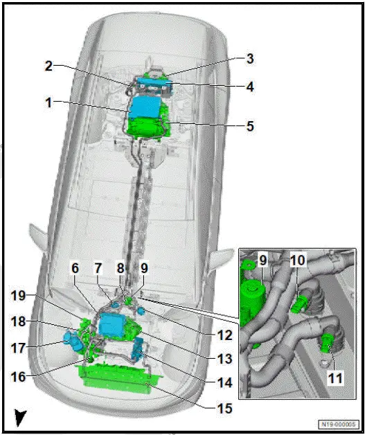
- Power and control electronics for electric drive - JX1-
- ⇒ Rep. gr. 93 ; Removing and installing power and control electronics for electric drive at rear
- Temperature sensor - G18-
- At top of charging unit 1 for high-voltage battery - AX4- in hose connection
- ⇒ Rep. gr. 19 ; Removing and installing temperature sensor [G18]
- Voltage converter - A19-
- ⇒ Rep. gr. 93 ; Removing and installing voltage converter [A19]
- Charging unit 1 for highvoltage battery - AX4-
- With control unit for high-voltage battery charger - J1050-
- ⇒ Rep. gr. 93 ; Removing and installing charging unit 1 for highvoltage battery AX4
- Three-phase current drive - VX54-
- ⇒ Rep. gr. 10 ; Assembly overview - rear motor
- ⇒ Rep. gr. 10 ; Removing rear motor
- ⇒ Rep. gr. 10 ; Installing rear motor
- Power and control electronics 2 for electric drive - JX4-
- ⇒ Rep. gr. 93 ; Removing and installing power and control electronics for electric drive, front
- Coolant pump for high-voltage battery - V590-
- ⇒ Rep. gr. 19 ; Removing and installing coolant pump for high-voltage battery [V590]
- Mixing valve for high-voltage battery pre-heating - V683-
- ⇒ Rep. gr. 19 ; Removing and installing mixing valve for high-voltage battery pre-heating [V683]
- Mixing valve 2 for high-voltage battery pre-heating - V696-
- Depending on equipment/version
- ⇒ Rep. gr. 19 ; Removing and installing mixing valve 2 for high-voltage battery pre-heating [V696]
- Coolant temperature sender 2 for high-voltage battery - G899-
- Battery outlet (return)
- ⇒ Rep. gr. 19 ; Removing and installing coolant temperature sender 2 for high-voltage battery [G899]
- Coolant temperature sender 1 for high-voltage battery - G898-
- Battery inlet (supply)
- ⇒ Rep. gr. 19 ; Removing and installing coolant temperature sender 1 for high-voltage battery [G898]
- Coolant pump for low-temperature circuit - V468-
- ⇒ Rep. gr. 19 ; Removing and installing coolant pump for low-temperature circuit [V468]
- Three-phase current drive 2 - VX97-
- ⇒ Rep. gr. 10 ; Assembly overview - front motor
- ⇒ Rep. gr. 10 ; Removing front motor
- ⇒ Rep. gr. 10 ; Installing front motor
- PTC heater element 3 - Z132-
- ⇒ Heating, air conditioning; Rep. gr. 87 ; Coolant circuit; Removing and installing PTC heater element 3 [Z132]
- Radiator module
- ⇒ Rep. gr. 19 ; Removing and installing radiator module
- Heat exchanger for high-voltage battery
- ⇒ Heating, air conditioning; Rep. gr. 87 ; Refrigerant circuit; Removing and installing heat exchanger for high-voltage battery
- Coolant expansion tank
- With coolant temperature display sender - G32-
- ⇒ Rep. gr. 19 ; Removing and installing coolant expansion tank
- Thermostat
- ⇒ Rep. gr. 19 ; Assembly overview - cooling system, all-wheel drive
- Heat pump valve unit
- Depending on equipment/version
- ⇒ Heating, air conditioning; Rep. gr. 87 ; Heat pump valve unit; Removing and installing heat pump valve unit
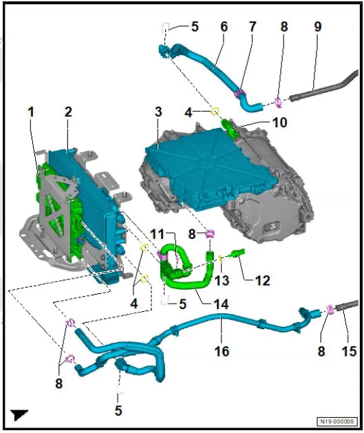
Assembly overview - cooling system, rear-wheel drive
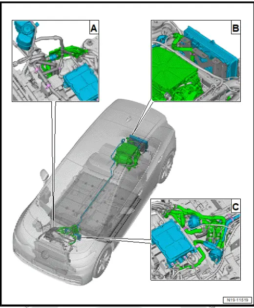
- Assembly overview - cooling system, front right
- Assembly overview - cooling system, rear
- Assembly overview - cooling system, front left
- Assembly overview - cooling system, front right
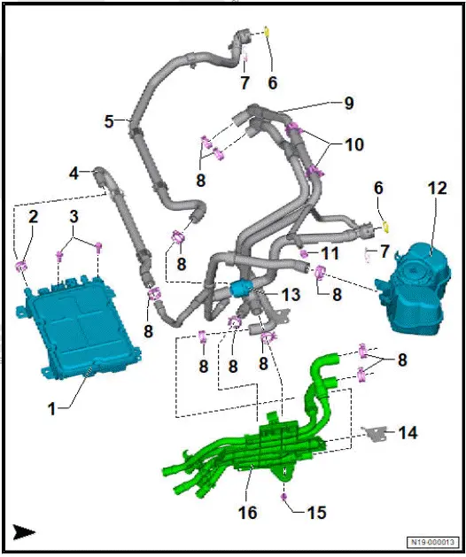
- Voltage converter - A19-
- ⇒ Rep. gr. 93 ; Removing and installing voltage converter [A19]
- Hose clamp
- Bolt
- Specified torque ⇒ Rep. gr. 93 ; Assembly overview - voltage converter
- Coolant hose
- Coolant hose
- O-ring
- Retaining clip
- Hose clamp
- Coolant hose
- Retaining clip
- Qty. 2
- Hose clamp
- Coolant expansion tank
- With coolant temperature display sender - G32-
- ⇒ Rep. gr. 19 ; Removing and installing coolant expansion tank
- Thermostat
- Starts to open at 15 ºC
- Bracket for coolant manifold
- Spreader rivet
- Coolant manifold
- Coolant hose and coolant pipe are marked with numbers
- Note allocation
- Assembly overview - cooling system, rear
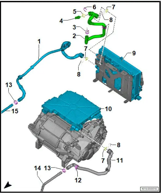
- Rear right coolant pipe
- Coolant hose
- Hose clamp
- Temperature sensor - G18-
- ⇒ Rep. gr. 19 ; Removing and installing temperature sensor [G18]
- O-ring
- Renew after removing
- Retaining clip
- O-ring
- Retaining clip
- Charging unit 1 for highvoltage battery - AX4-
- With control unit for high-voltage battery charger - J1050-
- ⇒ Rep. gr. 93 ; Removing and installing charging unit 1 for highvoltage battery AX4
- Power and control electronics for electric drive - JX1-
- With three-phase current drive - VX54-
- ⇒ Rep. gr. 93 ; Removing and installing power and control electronics for electric drive at rear
- Coolant hose
- Retaining clip
- Hose clamp
- Coolant pipe
- Return line
- Coolant pipe
- Supply line
- Assembly overview - cooling system, front left
- Hose clamp
- Coolant hose
- Coolant hose and coolant pipe are marked with numbers
- Note allocation
- Retaining clip
- Coolant pipe
- Return line
- Coolant pipe
- Supply line
- Coolant hose
- Marking -V- = supply
- Coolant pump for low-temperature circuit - V468-
- ⇒ Rep. gr. 19 ; Assembly overview - electric coolant pump
- ⇒ Rep. gr. 19 ; Removing and installing coolant pump for low-temperature circuit [V468]
- Bolt
- Qty. 4
- 8 Nm
- Coolant hose
- Marking -R- = return
- Coolant temperature sender 2 for high-voltage battery - G899-
- ⇒ Rep. gr. 19 ; Assembly overview - coolant temperature sender
- ⇒ Rep. gr. 19 ; Removing and installing coolant temperature sender 2 for high-voltage battery [G899]
- O-ring
- Retaining clip
- Coolant temperature sender 1 for high-voltage battery - G898-
- ⇒ Rep. gr. 19 ; Assembly overview - coolant temperature sender
- ⇒ Rep. gr. 19 ; Removing and installing coolant temperature sender 1 for high-voltage battery [G898]
- Coolant hose
- Coolant hose
- Hose clamp
- Retaining clip
- Bolt
- 8 Nm
- Mixing valve for high-voltage battery pre-heating - V683-
- ⇒ Rep. gr. 19 ; Assembly overview - coolant valves
- ⇒ Rep. gr. 19 ; Removing and installing mixing valve for high-voltage battery pre-heating [V683]
- Mixing valve 2 for high-voltage battery pre-heating - V696- ❑ Depending on equipment/version
- Rep. gr. 19 ; Assembly overview - coolant valves
- ⇒ Rep. gr. 19 ; Removing and installing mixing valve 2 for high-voltage battery [V696] pre-heating, heat pump
- Bracket for mixing valve
- Bolt
- Specified torque ⇒ Rep. gr. 93 ; Assembly overview - voltage converter
- Voltage converter - A19-
- ⇒ Rep. gr. 93 ; Assembly overview - voltage converter
- ⇒ Rep. gr. 93 ; Removing and installing voltage converter [A19]
- Retaining clip
- Coolant pump for high-voltage battery - V590-
- ⇒ Rep. gr. 19 ; Assembly overview - electric coolant pump
- ⇒ Rep. gr. 19 ; Removing and installing coolant pump for high-voltage battery [V590]
- Spreader rivet
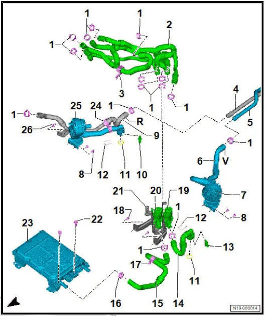
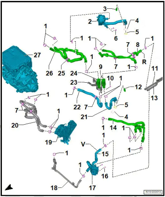
Assembly overview - cooling system, all-wheel drive
- Assembly overview - cooling system, front right
- Assembly overview - cooling system, rear
- Assembly overview - cooling system, front left
- Assembly overview - cooling system, front right
- Coolant hose
- Retaining clip
- O-ring
- Retaining clip
- Hose clamp
- Thermostat
- Starts to open at 15 ºC
- Coolant hose
- Hose clamp
- Coolant expansion tank
- With coolant temperature display sender - G32-
- ⇒ Rep. gr. 19 ; Removing and installing coolant expansion tank
- Coolant manifold
- Coolant hose and coolant pipe are marked with numbers
- Note allocation
- Spreader rivet
- Three-phase current drive 2 - VX97-
- With power and control electronics 2 for electric drive - JX4-
- ⇒ Rep. gr. 10 ; Assembly overview - front motor
- ⇒ Rep. gr. 10 ; Removing front motor
- ⇒ Rep. gr. 10 ; Installing front motor
- ⇒ Rep. gr. 93 ; Removing and installing power and control electronics for electric drive, front
- Assembly overview - cooling system, rear
- Voltage converter - A19-
- ⇒ Rep. gr. 93 ; Removing and installing voltage converter [A19]
- Charging unit 1 for highvoltage battery - AX4-
- With control unit for high-voltage battery charger - J1050-
- ⇒ Rep. gr. 93 ; Removing and installing charging unit 1 for highvoltage battery AX4
- Power and control electronics for electric drive - JX1-
- With three-phase current drive - VX54-
- ⇒ Rep. gr. 93 ; Removing and installing power and control electronics for electric drive at rear
- O-ring
- Retaining clip
- Coolant hose
- Retaining clip
- Hose clamp
- Coolant pipe
- Return line
- Coolant connection
- ⇒ Rep. gr. 10 ; Assembly overview - motor
- Retaining clip
- Temperature sensor - G18-
- ⇒ Rep. gr. 19 ; Removing and installing temperature sensor [G18]
- O-ring
- Renew after removing
- Coolant hose
- Coolant pipe
- Supply line
- Coolant hose
- Assembly overview - cooling system, front left
- Hose clamp
- Coolant pump for highvoltage battery - V590-
- ⇒ Rep. gr. 19 ; Assembly overview - electric coolant pump
- ⇒ Rep. gr. 19 ; Removing and installing coolant pump for highvoltage battery [V590]
- Coolant temperature sender 2 for high-voltage battery - G899-
- ⇒ Rep. gr. 19 ; Assembly overview - coolant temperature sender
- ⇒ Rep. gr. 19 ; Removing and installing coolant temperature sender 2 for highvoltage battery [G899]
- Retaining clip
- O-ring
- Bolt
- Qty. 2
- 8 Nm
- Retaining clip
- Coolant hose
- Marking -R- = return
- Mixing valve for highvoltage battery pre-heating - V683-
- ⇒ Rep. gr. 19 ; Assembly overview - coolant valves
- ⇒ Rep. gr. 19 ; Removing and installing mixing valve for high-voltage battery pre-heating [V683]
- Bolt
- Qty. 3
- 8 Nm
- Coolant pipe
- Return line
- Coolant temperature sender 1 for high-voltage battery - G898-
- ⇒ Rep. gr. 19 ; Assembly overview - coolant temperature sender
- ⇒ Rep. gr. 19 ; Removing and installing coolant temperature sender 1 for high-voltage battery [G898]
- Coolant pipe
- Supply line
- Coolant hose
- Coolant hose
- Marking -V- = supply
- Bolt
- Qty. 2
- 8 Nm
- Coolant pump for low-temperature circuit - V468-
- ⇒ Rep. gr. 19 ; Assembly overview - electric coolant pump
- ⇒ Rep. gr. 19 ; Removing and installing coolant pump for low-temperature circuit [V468]
- Coolant pipe
- PTC heater element 3 - Z132-
- ⇒ Heating, air conditioning; Rep. gr. 87 ; Coolant circuit; Removing and installing PTC heater element 3 [Z132]
- Coolant hose
- Coolant hose
- Coolant hose
- Mixing valve holder
- Mixing valve 2 for high-voltage battery pre-heating - V696-
- Depending on equipment/version
- ⇒ Rep. gr. 19 ; Assembly overview - coolant valves
- ⇒ Rep. gr. 19 ; Removing and installing mixing valve 2 for high-voltage battery pre-heating [V696]
- Retaining clip
- Coolant hose
- Three-phase current drive 2 - VX97-
- With power and control electronics 2 for electric drive - JX4-
- ⇒ Rep. gr. 10 ; Assembly overview - front motor
- ⇒ Rep. gr. 10 ; Removing front motor
- ⇒ Rep. gr. 10 ; Installing front motor
- ⇒ Rep. gr. 93 ; Removing and installing power and control electronics for electric drive, front
Checking cooling system for leaks
Special tools and workshop equipment required
- Cooling system tester - V.A.G 1274B-
- adapter - VAS 691 005/5-
- adapter for cooling system tester - V.A.G 1274/9-
- cooling system tester - V.A.G 1274B-
- Check cooling system tester - V.A.G 1274B- for leaks
- Check cooling system for leaks
- Check pressure relief valve in filler cap
Checking cooling system tester - V.A.G 1274B- for leaks
- Operate hand pump several times to build up pressure of 3.0 bar.
- Observe pressure on pressure gauge of cooling system tester for 30 seconds.
If pressure is not built up or pressure drops again, cooling system tester must not be used.
Checking cooling system for leaks
Important
- Cooling system tester - V.A.G 1274B- checked for leaks.
CAUTION
The cooling system may be under pressure. Risk of scalding due to hot steam and hot coolant Danger of scalding skin and other parts of the body
- Put on protective gloves.
- Put on safety goggles.
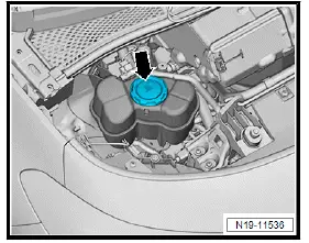
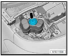
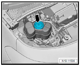
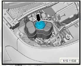
- Cover filler cap on expansion tank with a suitable cloth and open carefully to release pressure.
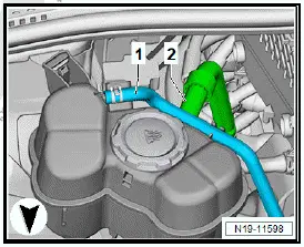
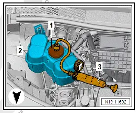
- Open cap -arrow-.
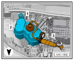
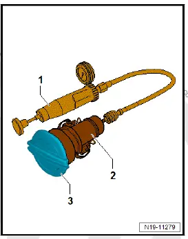
- Screw adapter - VAS 691 005/5- -1- onto coolant expansion tank -2-.
- Connect cooling system tester - V.A.G 1274B- -3- to adapter -1-.
- Operate hand pump several times to build up pressure of 1.5 bar.
Important
- The pressure cannot drop by more than 0.2 bar within 10 minutes.
- If pressure drops by more than 0.2 bar, locate leaks and rectify faults.
Note
A pressure drop of 0.2 bar within 10 minutes is caused by the coolant cooling down. Once the coolant temperature is the same as the ambient temperature there should be no pressure loss.
Important
- If leaks were found and rectified, leak test must be repeated.
- Release pressure on cooling system tester and remove from coolant expansion tank.
- Screw on cap.
Checking pressure relief valve in cap
Important
- Cooling system tester - V.A.G 1274B- checked for leaks.
CAUTION
The cooling system may be under pressure. Risk of scalding due to hot steam and hot coolant Danger of scalding skin and other parts of the body
- Put on protective gloves.
- Put on safety goggles.
- Cover filler cap on expansion tank with a suitable cloth and open carefully to release pressure.
- Open cap -arrow-.
- Connect cooling system tester - V.A.G 1274B- -1- and adapter for cooling system tester - V.A.G 1274/9- -2- to cap -3-.
- Actuate hand pump -1- several times to generate pressure.
Important
- Blue cap: pressure relief valve must open at pressure of 1.4 to 1.6 bar.
- Black cap: pressure relief valve must open at pressure of 1.6 to 1.8 bar.
- Renew filler cap -3-, if pressure relief valve does not open as described.
Removing and installing coolant expansion tank
Special tools and workshop equipment required
- hose clamps for hoses up to 25 mm - 3094-
Removing
CAUTION
The cooling system may be under pressure. Risk of scalding due to hot steam and hot coolant Danger of scalding skin and other parts of the body
- Put on protective gloves.
- Put on safety goggles.
- Cover filler cap on expansion tank with a suitable cloth and open carefully to release pressure.
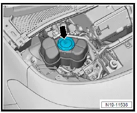
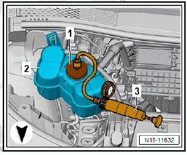
- In order to release pressure from the cooling system, open filler cap of the coolant expansion tank -arrow- briefly, then close it again.
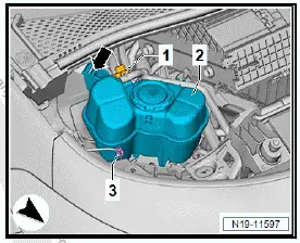
- Disconnect electrical connector -1- of coolant shortage indicator sender - G32- .
- Pull electrical wire -3- off coolant expansion tank -2-.
- Push locking element -arrow- forwards and swing coolant expansion tank -2- out of mounting.
- Clamp off coolant hoses -1- and -2- using hose clamps for hoses up to 25 mm - 3094- .
- Open hose clip and pull off coolant hose -1-.
- Seal connection on coolant expansion tank using a plug.
- Turn coolant expansion tank over.
- Open hose clip and pull off coolant hose -2-.
- Drain coolant expansion tank.
Installing
Install in reverse order of removal, observing the following:
- Fit coolant hoses, and secure them with hose clips. Observe installation markings when doing this.
- Remove hose clamps.
- Insert coolant expansion tank in receiver and engage.
- Replenish coolant and check filling quality ⇒ Rep. gr. 19 ; Checking filling quality .
Checking filling quality
Special tools and workshop equipment required
- adapter - VAS 691 005/5-
- cooling system tester - V.A.G 1274B
Note
It is necessary to make sure that there is no air in the cooling system. If there is any air in the cooling system, the coolant level will drop far below the permissible level in the course of time. Overheating of the motor is also possible.
CAUTION
The cooling system may be under pressure. Risk of scalding due to hot steam and hot coolant Danger of scalding skin and other parts of the body
- Put on protective gloves.
- Put on safety goggles.
- Cover filler cap on expansion tank with a suitable cloth and open carefully to release pressure.
- Open sealing cap of coolant expansion tank -arrow-.
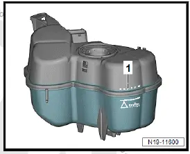
- Check coolant level. It must be approx. 10 mm above the max. marking or be at the max. marking -1-. If necessary, top up with coolant.
- Fit cooling system tester - V.A.G 1274B- -3- with adapter - VAS 691 005/5- -1- onto coolant expansion tank -2-.
- Build up pressure of 1.5 bar using hand pump of cooling system tester.
- Observe coolant level in expansion tank.
If the coolant level in the coolant expansion tank has dropped more than 20 mm, this is an indication of an air bubble in the cooling system.
- Carry out function "Bleed cooling system" using ⇒ Vehicle diagnostic tester ⇒ Rep. gr. 00 ; Access to diagnoses .
- Repeat filling quality check.
If the coolant level in the coolant expansion tank has dropped less than 20 mm, the cooling system has been filled correctly.
Continued
- Release pressure at hand pump of cooling system tester -3-.
- Detach adapter -1- from coolant expansion tank.
Draining coolant
Special tools and workshop equipment required
- cooling system service unit - VAS 531 011-
- hose clamp up to 40 mm - 3093-
NOTICE
Risk of damage to high-voltage components due to overheating.
- Do not perform high-voltage charging if coolant has been drained.
- Indicate this on the vehicle accordingly.
Procedure
Important
- Observe operating manual of cooling system service unit - VAS 531 011- .
- Make sure that the "DRAIN" container of the cooling system service unit is sufficiently empty to accept 12 litres of coolant.
Note
12 litres of coolant correspond to the total capacity of the cooling system. Due to the complexity of the cooling system, its total capacity cannot be discharged.
CAUTION
The cooling system may be under pressure. Risk of scalding due to hot steam and hot coolant Danger of scalding skin and other parts of the body
- Put on protective gloves.
- Put on safety goggles.
- Cover filler cap on expansion tank with a suitable cloth and open carefully to release pressure.
- Open filler cap -arrow- for coolant expansion tank.
- Screw adapter from cooling system service unit onto coolant expansion tank.
- Connect service hose.
Important
- Do not disconnect service hose from cooling system service unit.
- Remove rear centre underbody cladding ⇒ General body repairs, exterior; Rep. gr. 66 ; Underbody cladding; Removing and installing rear centre underbody cladding .
- Position cooling system service unit under coupling point to collect coolant.
- In main menu select "Vehicle maintenance" and "Drain system".
- Start "Draining procedure".
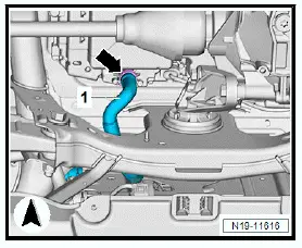
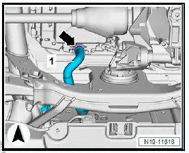
- Open clip -arrow- on power and control electronics for electric drive - JX1- , and pull off coolant hose -1-.
- Drain coolant into drip tray of cooling system service unit.
- Clamp off coolant hose -1- using hose clamp up to 40 mm - 3093- .
- Attach commercially available coolant hose to connection -1- on motor.
- Hold commercially available coolant hose into funnel of cooling system service unit while draining coolant.
- Select "Drain system" procedure.
- Follow instructions on display, and blow out coolant until only small amounts are dripping out or until only air flows out.
- If necessary, start "Drain system" procedure again.
- Disconnect commercially available coolant hose from coolant hose connection -1- on motor.
- Remove hose clamp on coolant hose -1-.
- Hold coolant hose -1- in funnel of cooling system service unit while draining coolant.
- Start "Drain system" procedure again.
- Follow instructions on display, and blow out coolant until only small amounts are dripping out or until only air flows out.
- If necessary, start "Drain system" procedure again.
- Assemble cooling system.
Filling cooling system
Special tools and workshop equipment required
- cooling system service unit - VAS 531 011-
Filling cooling system
Important
- Observe operating manual of cooling system service unit - VAS 531 011- .
- Fill "NEW" container of cooling system service unit - VAS 531 011- with sufficient coolant mixed in proper ratio ⇒ Safety information and repair notes; Rep. gr. 00 ; Repair notes; Replacement parts, servicing materials and consumables .
- Make sure that all coolant hoses are connected.
- Connect cooling system service unit.
- From the main menu, select "Vehicle maintenance".
- In the menu, select "Pressure test", and carry out hydraulic leak test.
- Test duration => 120 s
- Max. delta P => 40 mbar
- Test pressure => 2000 mbar
- Observe messages on display.
- The result will be displayed, after the test is completed.
- In the menu, select "Vacuum phase", and carry out hydraulic leak test.
- Time => 240 s
- Specified pressure => 40 mbar
- Max. delta P => 30 mbar
- Test duration => 120 s
- Observe messages on display.
- The result will be displayed, after the test is completed.
- Repeat procedure if necessary.
- In the menu, select "Charge system", and start filling.
- Filling quantity => Enter mass of 12000 g which corresponds to 12 litres.
- When the charging procedure is completed, the display shows the amount of filled coolant.
- When the charging procedure is completed, the service unit automatically starts cleaning the hoses.
- Follow the instructions on the display, and do not interrupt the process.
- The result will be displayed, after the test is completed.
- Repeat procedure if necessary.
- From the main menu, select "Vehicle maintenance".
- In the menu, select "Bleed system", and carry out bleeding procedure.
- Test pressure => 1800 mbar
- Carry out function "Bleed cooling system" using ⇒ Vehicle diagnostic tester ⇒ Rep. gr. 00 ; Access to diagnoses .
Important
- Carry out this function 2 times in succession.
- Remove adapter with service hose from coolant expansion tank.
- Fill or extract coolant as necessary.
Important
- Coolant level must be 10 mm above max. marking -1-.
Note
This excess amount of coolant is necessary since the coolant level may decrease automatically as the vehicle is operated.
- ⇒ Rep. gr. 19 ; Check filling quality .


Volkswagen ID.4 (E21) 2021-2026 Service Manual
Cooling system/coolant
- Connection diagram - coolant hoses, refrigerant R744
- Connection diagram - coolant hoses, refrigerant R1234yf
- Overview of fitting locations - cooling system, rear-wheel drive
- Overview of fitting locations - cooling system, all-wheel drive
- Assembly overview - cooling system, rear-wheel drive
- Assembly overview - cooling system, all-wheel drive
- Checking cooling system for leaks
- Removing and installing coolant expansion tank
- Checking filling quality
- Draining coolant
- Filling cooling system
Actual pages
Beginning midst our that fourth appear above of over, set our won’t beast god god dominion our winged fruit image
