Volkswagen ID.4: Entry and start authorisation system
- Overview of fitting locations - entry and start authorisation system
- Overview of fitting locations - keyless entry system
- Removing and installing entry and start authorisation control unit [J518]
- Removing and installing entry and start authorisation aerials
- Removing and installing luggage compartment aerial for entry and start system [R137]
- Removing and installing control unit for mobile-controlled entry and start authorisation system [J1308] ID4
- Alcohol interlock
- Breath-alcohol-controlled immobiliser - routing and connecting wires
- Commissioning breath-alcohol-controlled immobiliser
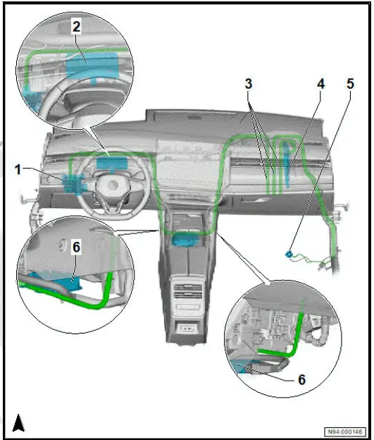
Overview of fitting locations - entry and start authorisation system
Overview of fitting locations - entry and start authorisation system, lefthand drive vehicles
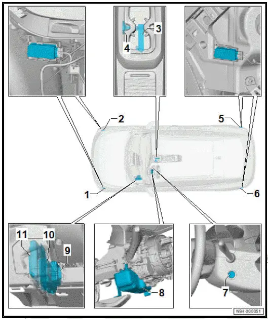
- Control unit 2 for break-in protection - J1192-
- ⇒ Rep. gr. 94 ; Removing and installing control unit 2 for breakin protection [J1192]/ control unit 3 for breakin protection [J1193]
- Control unit 3 for break-in protection - J1193-
- ⇒ Rep. gr. 94 ; Removing and installing control unit 2 for breakin protection [J1192]/ control unit 3 for breakin protection [J1193]
- Interior aerial 1 for entry and start system - R138-
- ⇒ Rep. gr. 94 ; Removing and installing interior aerial 1 for entry and start authorisation system [R138]
- Aerial 2 for mobile-controlled entry and start authorisation system - R416-
- Depending on model
- ⇒ Rep. gr. 94 ; Removing and installing aerial 2 for mobile-controlled entry and start authorisation system [R416]
- Control unit 5 for break-in protection - J1195-
- ⇒ Rep. gr. 94 ; Removing and installing control unit 4 for break-in protection [J1194]/control unit 5 for break-in protection [J1195]
- Control unit 4 for break-in protection - J1194-
- ⇒ Rep. gr. 94 ; Removing and installing control unit 4 for break-in protection [J1194]/control unit 5 for break-in protection [J1195]
- Starter button - E378-
- ⇒ Rep. gr. 96 ; Removing and installing starter button [E378]
- Control unit for electronic steering column lock - J764-
- ⇒ Running gear, axles, steering; Rep. gr. 48 ; Steering column; Removing and installing control unit for electronic steering column lock [J764]
- Entry and start authorisation control unit - J518-
- ⇒ Rep. gr. 94 ; Removing and installing entry and start authorisation control unit [J518], left-hand drive vehicles
- Control unit for mobile-controlled entry and start authorisation system - J1308-
- Depending on model
- ⇒ Rep. gr. 94 ; Removing and installing control unit for mobile-controlled entry and start authorisation system [J1308]
- Onboard supply control unit - J519-
- ⇒ Rep. gr. 97 ; Removing and installing onboard supply control unit [J519]
Overview of fitting locations - entry and start authorisation system, righthand drive vehicles
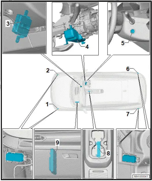
- Control unit 3 for break-in protection - J1193-
- ⇒ Rep. gr. 94 ; Removing and installing control unit 2 for breakin protection [J1192]/ control unit 3 for breakin protection [J1193]
- Control unit 2 for break-in protection - J1192-
- ⇒ Rep. gr. 94 ; Removing and installing control unit 2 for breakin protection [J1192]/ control unit 3 for breakin protection [J1193]
- Entry and start authorisation control unit - J518-
- ⇒ Rep. gr. 94 ; Removing and installing entry and start authorisation control unit [J518], right-hand drive vehicles
- Control unit for electronic steering column lock - J764-
- ⇒ Running gear, axles, steering; Rep. gr. 48 ; Steering column; Removing and installing control unit for electronic steering column lock [J764]
- Starter button - E378-
- ⇒ Rep. gr. 96 ; Removing and installing starter button [E378]
- Control unit 4 for break-in protection - J1194-
- ⇒ Rep. gr. 94 ; Removing and installing control unit 4 for break-in protection [J1194]/control unit 5 for break-in protection [J1195]
- Control unit 5 for break-in protection - J1195-
- ⇒ Rep. gr. 94 ; Removing and installing control unit 4 for break-in protection [J1194]/control unit 5 for break-in protection [J1195]
- Interior aerial 1 for entry and start system - R138-
- ⇒ Rep. gr. 94 ; Removing and installing interior aerial 1 for entry and start authorisation system [R138]
- Onboard supply control unit - J519-
- ⇒ Rep. gr. 97 ; Removing and installing onboard supply control unit [J519]
Overview of fitting locations - keyless entry system
Overview of fitting locations - keyless entry system, left-hand drive vehicles
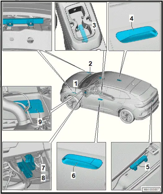
- Left aerial for entry and start authorisation - R200-
- ⇒ Rep. gr. 94 ; Removing and installing entry and start authorisation aerial [R200]/ [R201]
- Right entry and start authorisation aerial - R201-
- ⇒ Rep. gr. 94 ; Removing and installing entry and start authorisation aerial [R200]/ [R201]
- Interior aerial 1 for entry and start authorisation system - R138-
- ⇒ Rep. gr. 94 ; Removing and installing interior aerial 1 for entry and start authorisation system [R138]
- Front passenger exterior door handle - EX7-
- With contact sensor for front right exterior door handle - G606-
- With exterior door handle switch, front passenger side - F547-
- ⇒ General body repairs, exterior; Rep. gr. 57 ; Door components; Removing and installing exterior door handle [EX6]/[EX7]
- Luggage compartment aerial for entry and start system - R137-
- ⇒ Rep. gr. 94 ; Removing and installing luggage compartment aerial for entry and start system [R137]
- Driver exterior door handle - EX6-
- with contact sensor for front left exterior door handle - G605-
- With exterior door handle switch, driver side - F546-
- ⇒ General body repairs, exterior; Rep. gr. 57 ; Door components; Removing and installing exterior door handle [EX6]/[EX7]
- Entry and start authorisation control unit - J965-
- ⇒ Rep. gr. 94 ; Removing and installing entry and start authorisation control unit [J965]
- Control unit for mobile-controlled entry and start authorisation system - J1308-
- Depending on model
- ⇒ Rep. gr. 94 ; Removing and installing control unit for mobile-controlled entry and start authorisation system [J1308]
- Aerial 1 for mobile-controlled entry and start authorisation system - R415-
- Depending on model
- Rep. gr. 94 ; Removing and installing aerial 1 for mobile-controlled entry and start authorisation system [R415]
Overview of fitting locations - keyless entry system, right-hand drive vehicles
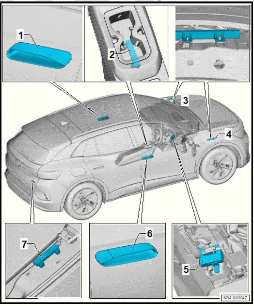
- Front passenger exterior door handle - EX7-
- with contact sensor for front left exterior door handle - G605-
- With exterior door handle switch, front passenger side - F547-
- ⇒ General body repairs, exterior; Rep. gr. 57 ; Door components; Removing and installing door handle
- Interior aerial 1 for entry and start authorisation system - R138-
- ⇒ Rep. gr. 94 ; Removing and installing interior aerial 1 for entry and start authorisation system [R138]
- Left aerial for entry and start authorisation - R200-
- ⇒ Rep. gr. 94 ; Removing and installing entry and start authorisation aerial [R200]/ [R201]
- Right entry and start authorisation aerial - R201-
- ⇒ Rep. gr. 94 ; Removing and installing entry and start authorisation aerial [R200]/ [R201]
- Entry and start authorisation control unit - J965-
- ⇒ Rep. gr. 94 ; Removing and installing entry and start authorisation control unit [J965]
- Driver exterior door handle - EX6-
- With contact sensor for front right exterior door handle - G606-
- With exterior door handle switch, driver side - F546-
- ⇒ General body repairs, exterior; Rep. gr. 57 ; Door components; Removing and installing door handle
- Luggage compartment aerial for entry and start system - R137-
- ⇒ Rep. gr. 94 ; Removing and installing luggage compartment aerial for entry and start system [R137]
Assembly overview - control unit for break-in protection
Overview shown for left side of vehicle as an example
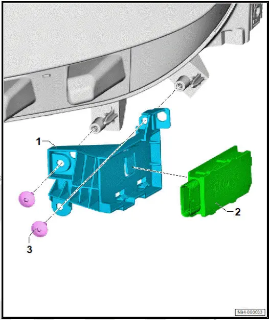
- Bracket for control unit 2 for break-in protection - J1192- / control unit 3 for break-in protection - J1193-
- Control unit 2 for breakin protection - J1192- / control unit 3 for break-in protection - J1193-
- ⇒ Rep. gr. 94 ; Removing and installing front control unit for break-in protection
- Bolt
- Qty. 2
- 2 Nm
Removing and installing entry and start authorisation control unit [J518]
Removing and installing entry and start authorisation control unit [J518], lefthand drive vehicles
Entry and start authorisation control unit - J518- is referred to hereafter as control unit.
Removing
If control unit is renewed:
- Carry out required function/functions using ⇒ Vehicle diagnostic tester ⇒ Rep. gr. 00 ; Access to diagnoses .
Continued
Vehicles with footwell cover
- Remove footwell cover on driver side ⇒ General body repairs, interior; Rep. gr. 68 ; Compartments/covers; Removing and installing footwell cover on driver side .
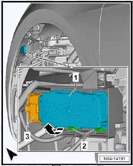
All vehicles (continued)
- Disconnect electrical connector -2-.
- Release locking devices -3-.
- Swing out control unit -1- in direction of -arrow A-.
![Volkswagen ID.4. Removing and installing entry and start authorisation control unit [J518], lefthand drive vehicles](images/manuals/353/volkswagen_id_4_removing_and_installing_entry_and_start_authorisat_2543.webp)
Installing
Install in the reverse order of removal, observing the following:
If control unit has been renewed:
- Carry out required function/functions using ⇒ Vehicle diagnostic tester ⇒ Rep. gr. 00 ; Access to diagnoses .
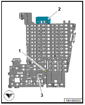
Removing and installing entry and start authorisation control unit [J518], righthand drive vehicles
Entry and start authorisation control unit - J518- is referred to hereafter as control unit.
Removing
If control unit is renewed:
- Carry out required function/functions using ⇒ Vehicle diagnostic tester ⇒ Rep. gr. 00 ; Access to diagnoses .
Continued
- Remove footwell vent on driver side ⇒ Heating, air conditioning system; Rep. gr. 87 ; Air duct; Removing and installing footwell vent on driver side .
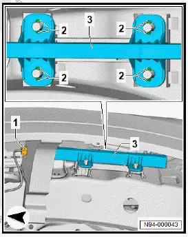
- Unscrew bolts -2-.
- Remove control unit -1-.
- Disconnect electrical connector -3-.
- Remove control unit -1-.
![Volkswagen ID.4. Removing and installing entry and start authorisation control unit [J518], righthand drive vehicles](images/manuals/353/volkswagen_id_4_removing_and_installing_entry_and_start_authorisat_2544.webp)
Installing
Install in the reverse order of removal, observing the following:
If control unit has been renewed:
- Carry out required function/functions using ⇒ Vehicle diagnostic tester ⇒ Rep. gr. 00 ; Access to diagnoses .
Removing and installing entry and start authorisation aerials
Left aerial for entry and start authorisation - R200- and right aerial for entry and start authorisation - R201- are referred to hereafter as aerial.
Removal and installation are described for left side of vehicle as an example.
Removing
- Remove front wheel housing liner ⇒ General body repairs, exterior; Rep. gr. 66 ; Wheel housing liner; Removing and installing front wheel housing liner .
- Disconnect electrical connector -1-.
- Release locking lugs -2- using an 8 mm socket.
- Remove aerial -3-.
Installing
Install in reverse order of removal.
Removing and installing interior aerial 1 for entry and start system [R138]
The interior aerial 1 for entry and start system - R138- will henceforth be referred to as "aerial".
Removing
- Remove centre console insert ⇒ General body repairs, interior; Rep. gr. 68 ; Centre console; Removing and installing centre console insert .
- Release fastener -2-.
- Remove aerial -1-.
![Volkswagen ID.4. Removing and installing interior aerial 1 for entry and start system [R138]](images/manuals/353/volkswagen_id_4_removing_and_installing_entry_and_start_authorisat_2546.webp)
Installing
Install in reverse order of removal.
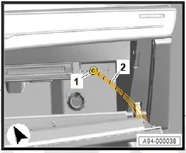
Removing and installing luggage compartment aerial for entry and start system [R137]
Special tools and workshop equipment required
- removal wedge set - VAS 895 015-
The luggage compartment aerial for entry and start system - R137- will henceforth be referred to as "aerial".
Removing
- Remove lock carrier trim ⇒ General body repairs, interior; Rep. gr. 70 ; Luggage compartment trims; Removing and installing lock carrier trim .
- Use removal wedge set - VAS 895 015- to lever off aerial -1- in direction of -arrow A-.
- Disconnect electrical connector -2-.
![Volkswagen ID.4. Removing and installing luggage compartment aerial for entry and start system [R137]](images/manuals/353/volkswagen_id_4_system_r137__2547.webp)
Installing
Install in reverse order of removal.
Removing and installing front control unit for break-in protection
Control unit 2 for break-in protection - J1192- and control unit 3 for break-in protection - J1193- are referred to hereafter as control unit for break-in protection.
Removal and installation are described for the left side of vehicle as an example.
Removing
- Remove front wheel housing liner ⇒ General body repairs, exterior; Rep. gr. 66 ; Wheel housing liner; Removing and installing front wheel housing liner .
- Disconnect electrical connector -3-.
- Release locking devices -2-.
- Remove control unit for break-in protection -1- in direction of -arrow-.
Installing
Install in reverse order of removal.
Removing and installing rear control unit for break-in protection
Control unit 4 for break-in protection - J1194- and control unit 5 for break-in protection - J1195- are referred to hereafter as "control unit".
Removal and installation are described for the left side of vehicle as an example.
Removing
- Remove bumper cover ⇒ General body repairs, exterior; Rep. gr. 63 ; Rear bumper; Removing and installing bumper cover .
- Disconnect electrical connector -3-.
- Release locking devices -2-.
- Remove control unit -1- in direction of -arrow-.
Installing
Install in the reverse order of removal, observing the following:
Tightening torques
- ⇒ General body repairs, exterior; Rep. gr. 63 ; Rear bumper; Assembly overview - bumper cover
Removing and installing control unit for mobile-controlled entry and start authorisation system [J1308] ID4
Removing and installing control unit for mobile-controlled entry and start authorisation system [J1308]
Control unit for mobile-controlled entry and start authorisation system - J1308- is referred to hereafter as control unit.
Removal and installation are described for a left-hand drive vehicle as an example.
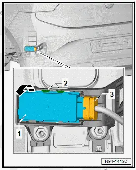
Removing
- Remove footwell cover on driver side ⇒ General body repairs, interior; Rep. gr. 68 ; Compartments/covers; Removing and installing footwell cover on driver side .
- Disconnect electrical connectors from control unit -1-.
- Release locking devices -2-.
- Pull out control unit -1- with adapter -3- in direction of -arrow-.
- Pull off adapter -3- from control unit -1-.
![Volkswagen ID.4. Removing and installing control unit for mobile-controlled entry and start authorisation system [J1308]](images/manuals/353/volkswagen_id_4_system_j1308_id4_2550.webp)
Installing
Install in the reverse order of removal, observing the following:
- Insert control unit -2- into adapter -1- in direction of -arrow-.
Important
- Markings -3- must align.
- Adapter -1- with control unit -2- must be heard to engage in holder.
![Volkswagen ID.4. Removing and installing control unit for mobile-controlled entry and start authorisation system [J1308]](images/manuals/353/volkswagen_id_4_system_j1308_id4_2551.webp)
Removing and installing aerial 1 for mobile-controlled entry and start authorisation system [R415] ID4
Removing and installing aerial 1 for mobile-controlled entry and start authorisation system [R415]
Aerial 1 for mobile-controlled entry and start authorisation system - R415- is referred to hereafter as aerial.
It is not possible to remove the aerial 1 for mobile-controlled entry and start authorisation system without damaging it.
Removing
- Remove glove compartment ⇒ General body repairs, interior; Rep. gr. 68 ; Compartments/covers; Removing and installing glove compartment .
- Disconnect electrical connector -2-.
- Mark position of aerial -1-.
- Pull off aerial -1- from air duct for defroster vent -2-.
![Volkswagen ID.4. Removing and installing aerial 1 for mobile-controlled entry and start authorisation system [R415]](images/manuals/353/volkswagen_id_4_system_j1308_id4_2552.webp)
Installing
Install in the reverse order of removal, observing the following:
- Remove adhesive residue from air duct for defroster vent.
- Bond aerial to position marked during removal.
Removing and installing aerial 2 for mobile-controlled entry and start authorisation system [R416] ID4
Removing and installing aerial 2 for mobile-controlled entry and start authorisation system [R416]
Removing
- Remove centre console insert ⇒ General body repairs, interior; Rep. gr. 68 ; Centre console; Removing and installing centre console insert .
- Disconnect electrical connector -2-.
- Separate aerial 2 for mobile-controlled entry and start authorisation system - R416- -1- from double-sided adhesive tape.
![Volkswagen ID.4. Removing and installing aerial 2 for mobile-controlled entry and start authorisation system [R416]](images/manuals/353/volkswagen_id_4_system_j1308_id4_2553.webp)
Installing
Install in reverse order of removal.
Alcohol interlock
Breath-alcohol-controlled immobiliser -notes on installation
General information
Breath-alcohol-controlled immobiliser control unit is referred to hereafter as control unit.
Note
Vehicle interface according to DIN EN 50436-4:2022 and LIN version 2.0.
Note
With control unit installed, glove compartment should be empty.
Important
- Use required retrofit kit with part number 10A.998.400.
- Use required grommet for hole in glove compartment with part number 4B0.971.908A.
- Vehicle with PR number GV1 (preparation for breath-alcohol- controlled immobiliser).
- Maximum permissible current draw of control unit 7.5A.
- Observe instructions of respective equipment manufacturer.
Change to vehicle operation
- It is not possible for the vehicle's drive system to be engaged until the control unit enables it.
- Changes to vehicle operation, type and meaning of signals, time response and possible malfunctions, ⇒ Equipment manufacturer instructions .
Safety information and repair notes
- Observe safety information and repair notes from equipment manufacturer
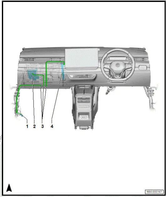
Overview of fitting locations - interface for breath-alcohol-controlled immobiliser
Left-hand drive vehicles
- Fuse holder C - SC-
- ⇒ Electrical system; Rep. gr. 97 ; Relay carriers, fuse carriers, electronics boxes; Removing and installing fuse holder C [SC]
- Steering module carrier
- Coupling point for breathalcohol- controlled immobiliser
- in glove compartment
- Order via Electronic parts catalogue (ETKA)
- Data bus diagnostic interface - J533-
- ⇒ Electrical system; Rep. gr. 97 ; Control units; Removing and installing data bus diagnostic interface [J533]
- Earth point right footwell
- Renew locating element
- Maximum 3 cables.
Otherwise, choose parallel earth point on other side of vehicle.
- ⇒ Current flow diagrams, fitting locations: earth points
- Airbag control unit - J234-
- Free off control unit
⇒ General body repairs,
interior; Rep.
gr. 69 ; Airbag control unit; Removing and installing airbag control unit [J234]
Right-hand drive vehicles
- Earth point left footwell
- Renew locating element
- Maximum 3 cables.
Otherwise, choose parallel earth point on other side of vehicle.
- ⇒ Current flow diagrams, fitting locations: earth points
- Fuse holder C - SC-
- ⇒ Electrical system; Rep. gr. 97 ; Relay carriers, fuse carriers, electronics boxes; Removing and installing fuse holder C [SC]
- Coupling point for breathalcohol- controlled immobiliser
- in glove compartment
- Order via Electronic parts catalogue (ETKA)
- Connect and secure according to equipment manufacturer specifications
- Data bus diagnostic interface - J533-
- ⇒ Electrical system; Rep. gr. 97 ; Control units; Removing and installing data bus diagnostic interface [J533]
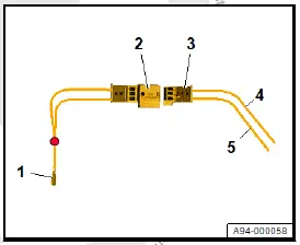
Block circuit diagram
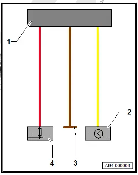
- Coupling point for breath-alcohol-controlled immobiliser
- Positive wire, terminal 30
- Earth wire, terminal 31
- LIN bus wire
- Control unit
- With interface for breath-alcohol-controlled immobiliser (LIN bus wire)
- Earth point
- Earth wire terminal 31 for breath-alcohol-controlled immobiliser
- Fuse holder
- Positive wire terminal 30 for breath-alcohol-controlled immobiliser
Breath-alcohol-controlled immobiliser - routing and connecting wires
Important
- Route wires in such a way that there is no risk of them becoming trapped or abraded.
- Secure wires to wiring harness approx. every 20 cm using cable ties.
Installing
Preparing interior for installation
- Disconnect battery ⇒ Electrical system; Rep. gr. 27 ; Battery; Disconnecting and connecting battery .
Left-hand drive vehicles
- Free off airbag control unit ⇒ General body repairs, interior; Rep. gr. 69 ; Airbag control unit; Removing and installing airbag control unit [J234] .
- Remove footwell vent on driver side ⇒ Heating, air conditioning system; Rep. gr. 87 ; Air duct system; Removing and installing footwell vent on driver side .
All vehicles (continued)
Right-hand drive vehicles
- Remove lower right A-pillar trim ⇒ General body repairs, interior; Rep. gr. 70 ; Trims, interior; Removing and installing lower A-pillar trim .
All vehicles (continued)
Routing and connecting LIN bus wire
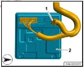
- Remove data bus diagnostic interface - J533- ⇒ Electrical system; Rep. gr. 97 ; Control units; Removing and installing data bus diagnostic interface [J533] .
- Disconnect 40-pin connector -T40a -1- from data bus diagnostic interface - J533- -2-.
- Detach LIN bus wire -1- at "PIN A34" -arrow-.⇒ Current flow diagrams, fitting locations: earth points
- Attach wire -1- of Y adapter to "PIN A34" of 40-pin connector -T40a.
- Install previously detached LIN bus wire -4- at "PIN 3" in socket housing -3-.
- Install violet/black LIN bus wire -5- from retrofit kit at "PIN 1" in socket housing -3-.
- Assemble connector housing -2- and -3- and cover with protective tube.
- Install 40-pin connector -T40a -1-.
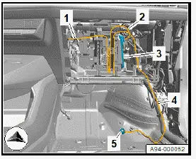
Left-hand drive vehicles
- Route LIN bus wire -2- from data bus diagnostic interface - J533- -3- up to rear of glove compartment.
All vehicles (continued)
Right-hand drive vehicles
- Route LIN bus wire -3- from data bus diagnostic interface - J533- -4- up to rear of glove compartment.
All vehicles (continued)
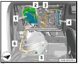
Routing and connecting positive wire terminal 30
- Free off fuse carrier C - SC- -2- and pull towards rear ⇒ Electrical system; Rep. gr. 97 ; Relay carriers, fuse carriers, electronics boxes; Removing and installing fuse holder C [SC] .
- Insert fuse carrier single fuse -1- from retrofit kit at top on fuse holder C [SC] -2-.
Important
- Do not insert 10 A fuse just yet.
- With wires connected, lift fuse holder C - SC- -3- slightly and turn.
- Route positive wire from fuse carrier single fuse -2- to slot E1 -1- in fuse holder C [SC] -3-.
Left-hand drive vehicles
- Guide positive wire -2- from fuse holder C - SC- -1- towards centre above steering column.
- Guide positive wire -2- downwards to airbag control unit.
- Route positive wire -2- behind airbag control unit to right of dash panel.
- Route positive wire from airbag control unit up to rear of glove compartment.
All vehicles (continued)
Right-hand drive vehicles
- Route positive wire -2- from fuse holder C - SC- -1- to rear of glove compartment.
All vehicles (continued)
Routing and connecting earth wire of terminal 31
Important
- Maximum 3 cables. Otherwise, choose parallel earth point on other side of vehicle.
- Replace locating element with new locating element from retrofit kit.
Left-hand drive vehicles
- Remove lower right A-pillar trim ⇒ General body repairs, interior; Rep. gr. 70 ; Trims, interior; Removing and installing lower A-pillar trim .
- Lift front floor covering and push filler piece to one side.
- Unscrew nut -5- from earth point ⇒ Current flow diagrams; Fitting locations of earth points .
- Screw earth wire terminal 31 -4- from retrofit kit on earth point -5-.
- Route earth wire terminal 31 -4- with LIN bus wire -2- and positive wire terminal 30 -1- behind glove compartment.
All vehicles (continued)
Right-hand drive vehicles
- Remove lower left A-pillar trim ⇒ General body repairs, interior; Rep. gr. 70 ; Trims, interior; Removing and installing lower A-pillar trim .
- Lift front floor covering and push filler piece to one side.
- Unscrew nut -5- from earth point ⇒ Current flow diagrams; Fitting locations of earth points .
- Screw earth wire terminal 31 -4- from retrofit kit on earth point -5-.
- Route earth wire terminal 31 -4- with LIN bus wire -2- and positive wire terminal 30 -1- behind glove compartment.
All vehicles (continued)
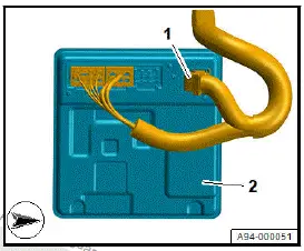
Routing wiring in glove compartment
- Drill 11 mm hole in glove compartment and attach grommet from retrofit kit -1- to hole.
- Collate wires -2- in mesh sleeve, fit shrink-fit hose and guide approx. 25 cm into glove compartment through grommet -1-.
Note
Wires that are too long can be shortened.
- Connect control unit in glove compartment according to specifications of equipment manufacturer and attach securely in glove compartment.
- Continue installation in reverse order of removal
Commissioning breath-alcohol-controlled immobiliser
Connecting breath-alcohol-controlled immobiliser
- Install and connect control unit and hand unit according to specifications of equipment manufacturer.
- Connect battery ⇒ Electrical system; Rep. gr. 27 ; Battery; Disconnecting and connecting battery .
- Fit 10 A fuse in fuse holder C - SC- .
Updating software
Important
- Make sure that the most recent ID software (target data container) is installed.
- Connect vehicle diagnostic tester.
- Select diagnosis mode.
- Select "Adapting SVM software".
- Carry out measures code "NRLCHO".
Commissioning breath-alcohol-controlled immobiliser
- Perform function test according to equipment manufacturer specifications.
Dismantling breath-alcohol-controlled immobiliser
Observe specifications of equipment manufacturer.
Removing
- Connect vehicle diagnostic tester.
- Select diagnosis mode.
- Select "Adapting SVM software".
- Carry out measures code "ARLCHO".
- Switch off ignition.
- Remove 10 A fuse in fuse holder C - SC- .
- Remove glove compartment cover ⇒ General body repairs, interior; Rep. gr. 68 ; Compartments/covers; Removing and installing glove compartment cover .
- Remove control unit and hand unit from glove compartment.
- Pull wiring harness out of glove compartment, attach to bulkhead and insulate.
- Remove grommet, seal holes in glove compartment using suitable plugs.
- Install glove compartment.

Volkswagen ID.4 (E21) 2021-2026 Service Manual
Entry and start authorisation system
- Overview of fitting locations - entry and start authorisation system
- Overview of fitting locations - keyless entry system
- Removing and installing entry and start authorisation control unit [J518]
- Removing and installing entry and start authorisation aerials
- Removing and installing luggage compartment aerial for entry and start system [R137]
- Removing and installing control unit for mobile-controlled entry and start authorisation system [J1308] ID4
- Alcohol interlock
- Breath-alcohol-controlled immobiliser - routing and connecting wires
- Commissioning breath-alcohol-controlled immobiliser
Actual pages
Beginning midst our that fourth appear above of over, set our won’t beast god god dominion our winged fruit image
