Volkswagen ID.4: Sliding sunroof
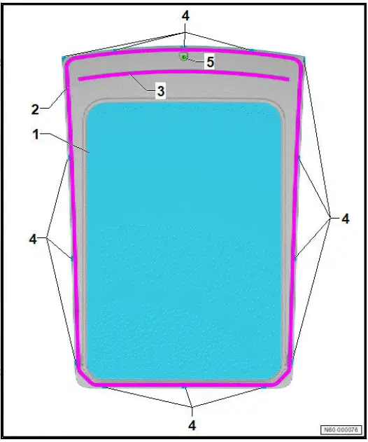
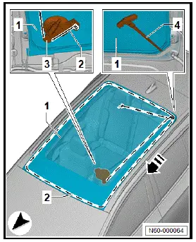
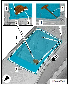
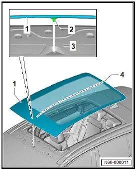
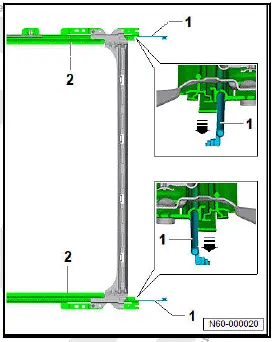
Assembly overview - glass panel
- Glass panel
- ⇒ Rep. gr. 60 ; Removing and installing glass panel
- Outer bonding surface
- Centre bonding surface
- Fitted on selected models
- Spacer
- Depending on equipment/ version
- Centring pin
- Assembly overview - sun blind
- Removing and installing glass panel
- Removing and installing frame with sun blind
- Removing and installing sun blind
- Removing and installing sun blind drive unit VX455
- Removing and installing sun blind cables
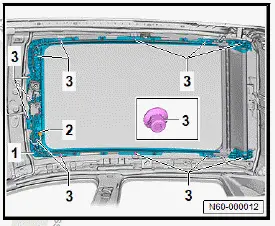
Assembly overview - sun blind
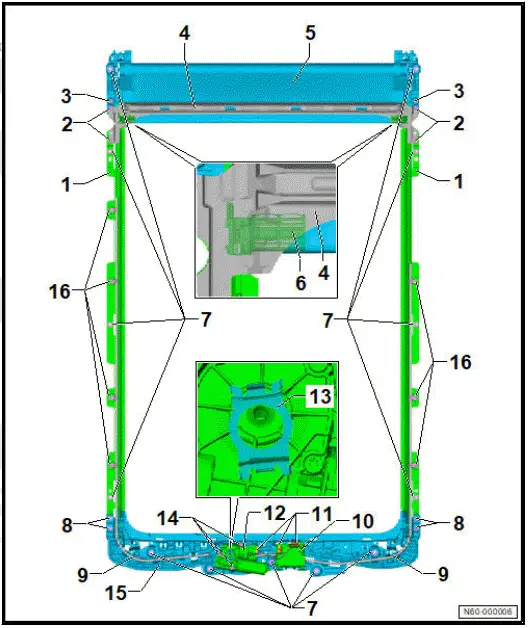
- Side frame section
- Part of frame with sun blind
- ⇒ Rep. gr. 60 ; Removing and installing frame with sun blind
- Bolt
- Qty. 4
- Renew after removing
- 5.5 Nm
- Bolt
- Qty. 2
- Renew after removing
- 5.5 Nm
- Rear frame section
- Part of frame with sun blind
- ⇒ Rep. gr. 60 ; Removing and installing frame with sun blind
- Sun blind
- ⇒ Rep. gr. 60 ; Removing and installing sun blind
- Slide
- Nut
- Qty. 13
- Renew after removing
- Specified torque and tightening sequence
- Bolt
- Qty. 4
- Renew after removing
- 5.5 Nm
- Sun blind cable
- ⇒ Rep. gr. 60 ; Removing and installing sun blind cables
- Roof system control unit - J1355-
- ⇒ Rep. gr. 60 ; Removing and installing roof system control unit J1355
- ⇒ Rep. gr. 60 ; Adapting roof system adjustment control unit J1355
- Electrical connector
- Sun blind drive unit - VX455-
- With Hall sender 1 for sun blind motor - G1193-
- With Hall sender 2 for sun blind motor - G1194-
- With sun blind motor - V758-
- ⇒ Rep. gr. 60 ; Removing and installing sun blind drive unit VX455
- Spring plate
- Bolt
- Qty. 3
- 4 Nm
- Front frame section
- Part of frame with sun blind
- ⇒ Rep. gr. 60 ; Removing and installing frame with sun blind
- Clip
- Qty. 7
Removing and installing glass panel
Special tools and workshop equipment required
- cutting cord - VAS 861 001/1A-
- hot air blower - V.A.G 1416-
- setting gauge - 3371-
- suction lifter - V.A.G 1344-
- window removal kit - VAS 861 001A
CAUTION
Risk of injury to hands and eyes due to glass splinters.
Danger of cutting yourself.
- Put on safety goggles.
- Put on protective gloves.
NOTICE
Risk of damage to surfaces of components.
- Mask off surrounding components in the visible area with commercially available adhesive tape.
Removal is described using window removal kit - VAS 861 001A- .
Removing
- Open sun blind.
- Using commercially available adhesive tape, form a stop 3 cm from the pointed end of the awl -4- from window removal set - VAS 861 001A- .
- Insert cutting cord - VAS 861 001/1A- -2- in awl -4-.
- Using commercially available adhesive tape, form a stop 3 cm from the pointed end of the awl -4- from window removal set - VAS 861 001A- .
- Insert cutting cord - VAS 861 001/1A- -2- in awl -4-.
NOTICE
Penetrating adhesive bead with awl Damage to paintwork on body flange
- Mask off exit area of awl -4- on body flange using adhesive tape.
- A second person exposes the exit area of the glass panel seal on the outside at the penetration point using a commercially available plastic wedge and monitors the penetration.
- Observe stop on awl -4- during penetration.
- Pierce adhesive bead with awl -4- from inside to outside, and pull through cutting cord -2- towards outside.
- Coat seal of glass panel -1- with soapy solution.
- Lay cutting cord -2- under glass panel around entire circumference -1- while at the same time clearing off glass panel seal -1- using commercially available plastic wedge.
- Insert cutting cord -2- under glass panel seal -1-.
- Press down windscreen seal using commercially available plastic wedge.
- Insert cutting cord -2- between glass panel -1- and windscreen with threading-in aid.
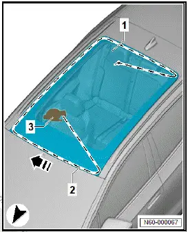
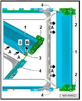
- Mask off contact surface of cutting cord -1- on hinge -2- using commercially available adhesive tape.
- Secure outer end of cutting cord -1- on left hinge -2- -arrow-
- Secure cutting out device -3- to inside of glass panel -1- at front left.
- Insert cutting cord -2- into cutting out device -3-.
- Tension cutting cord -2- with cutting out device -3-.
Important
- The aid of an additional person is required for the subsequent work steps.
- Cut free side section of glass panel -1- in direction of -arrowusing cutting cord -2- while having the second person guide cutting cord -2- past components.
Important
- The aid of an additional person is required for the subsequent work steps.
Note
Glass panel -1- can also be reused without centring pin -2-.
- Cut through adhesive bead around centring pin -2- while having the second person guide cutting cord -2- past components.
- Secure cutting out device -3- to inside of glass panel -1- at front right.
Note
There are two adhesive beads in the front area between the glass panel -1- and roof cross member. Greater force is necessary when cutting through in these areas.
- Heat up glass panel -1- in area of adhesive beads to 40 ºC (104 ºF) using hot air blower - V.A.G 1416- .
Important
- The aid of an additional person is required for the subsequent work steps.
- Cut free front section of glass panel -1- in direction of -arrowusing cutting cord -2- while having the second person guide cutting cord -2- past components.
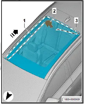
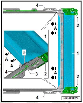
- Secure cutting out device -2- to inside of glass panel -1- at rear right.
Important
- The aid of an additional person is required for the subsequent work steps.
- Cut free side section of glass panel using cutting cord -3- in direction of -arrow- while having the second person guide cutting cord -3- past components.
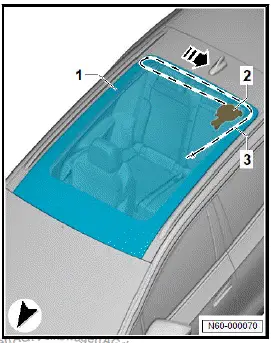
- Secure cutting out device -2- to inside of glass panel -1- at rear right.
Important
- The aid of an additional person is required for the subsequent work steps.
- Cut free rear section of glass panel using cutting cord -3- in direction of -arrow- while having the second person guide cutting cord -3- past components.
Important
- The aid of four additional persons is required for the subsequent work steps.
- Lift glass panel out of vehicle using two suction lifters - V.A.G 1344- .
Installing
Undamaged glass panel
- ⇒ General information - body; Rep. gr. 52 ; Use of adhesives; Preparing undamaged windows for installation .
All vehicles (continued)
New glass panel
Note
Bonding surface is marked on glass panel.
- Clean bonding surfaces, let them dry, and apply primer ⇒ General information - body; Rep. gr. 52 ; Use of adhesives; Preparing new windows for installation .
All vehicles (continued)
- ⇒ General information - body; Rep. gr. 52 ; Use of adhesives; Preparing body flange for installation .
- Observe ⇒ General information - body; Rep. gr. 52 ; Use of adhesives; Installation instructions for bonded windows .
- Observe ⇒ Rep. gr. 60 ; Minimum drying time for bonded glass panels .
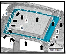
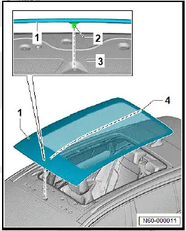
Glass panel -1- can also be installed without spacers -3
Important
- Outlet nozzle of cartridge ⇒ Electronic parts catalogue (ETKA) must be adapted using suitable workshop equipment to ensure bead cross-section as per specification.
- Apply window adhesive -2- to marked bonding surface of glass panel -1-.
Dimensions for cross-section of adhesive bead:
- Dimension -a-: 8 +- 2 mm
- Dimension -b-: 13.5 +- 1.5 mm
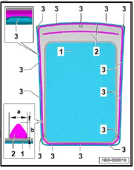
- Bond windscreen seal sealing lip to windscreen using commercially available adhesive tape.
Important
- The aid of four additional persons is required for the subsequent work steps.
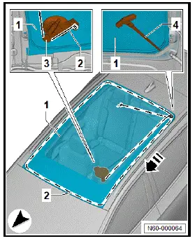
- Insert glass panel -1- into roof aperture -3- using suction lifter - V.A.G 1344- .
Important
- Glass panel -1- must be fitted within 10 minutes after application of adhesive. Failure to adhere to timing will impair adhesive properties of window adhesive.
- Align glass panel -1- centrally -2- in roof aperture -3- via centring pin -4-.
If there is no centring pin -2-, align glass panel -1- centrally in roof aperture -3- as shown in illustration -4-.
- Push down glass panel -1- onto spacers.
- Check gaps using setting gauge - 3371- . Observe ⇒ Rep. gr. 00 ; Gaps - roof for this.
- Remove adhesive tape from windscreen seal sealing lip so that correct position of sealing lip is assured.
Continue installation in reverse order of removal.
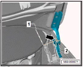
Removing and installing frame with sun blind
Removing
- Remove moulded headliner ⇒ General body repairs, interior; Rep. gr. 70 ; Roof trims; Removing and installing moulded headliner .
- Disconnect electrical connector -2-.
Important
- The aid of an additional person is required for the subsequent work steps.
- Unscrew nuts -3-, and remove slotted guide -1- from vehicle.
Installing
Install in reverse order of removal, observing the following:
Tightening torques
- ⇒ Rep. gr. 60 ; Assembly overview - sun blind
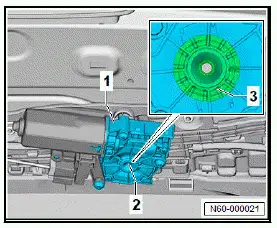
Removing and installing roof system control unit J1355
Roof system control unit - J1355- is referred to hereafter as control unit.
Removing
- Lower the moulded headliner, and place it on head restraints ⇒ General body repairs, interior; Rep. gr. 70 ; Roof trims; Removing and installing moulded headliner .
If the control unit is renewed, perform the test plan for renewal of the control unit:
- Carry out function "Renew control unit" using ⇒ Vehicle diagnostic tester ⇒ Rep. gr. 00 ; Access to diagnoses .
Continued
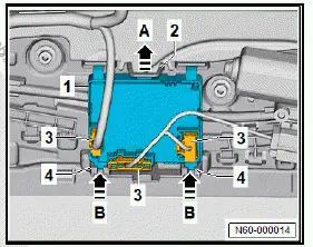
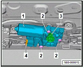
- Disconnect electrical connectors -3-.
- Push tab -2- in direction of -arrow A-.
- Swing control unit -1- downwards, and pull it in direction of -arrow B- out of retainers -4-.
Installing
Install in reverse order of removal, observing the following:
- Conclude function "Renew control unit" using ⇒ Vehicle diagnostic tester ⇒ Rep. gr. 00 ; Access to diagnoses .
Removing and installing sun blind
Removing
- Open sun blind completely.
If the electrical system fails to operate, the sun blind can also be opened manually ⇒ Rep. gr. 60 ; Manual operation .
- Remove moulded headliner ⇒ General body repairs, interior; Rep. gr. 70 ; Roof trims; Removing and installing moulded headliner .
- Remove sun blind drive unit - VX455- ⇒ Rep. gr. 60 ; Removing and installing sun blind drive unit VX455 .
- Remove frame with sun blind ⇒ Rep. gr. 60 ; Removing and installing frame with sun blind .
- Push sun blind -2- by hand as far as possible towards rear in direction of -arrow A-.
- Unscrew bolts -1-.
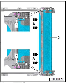
- Pull sun blind -1- together with holders -2- in direction of -arrow A- out of sun blind frame -4- until connecting point between sun blind -1- and cables -3- becomes visible.
- Detach cables -3- from slides -5- in direction of -arrow B-.
Installing
Install in reverse order of removal, observing the following:
Important
- Sun blind -1- always remains attached to holders -2-.
- Attach cables -3- to slides -5- in sun blind -1-.
- Push sun blind -1- with attached cables -3- in direction of -arrow A- in sun blind frame -4-.
- Adapt ⇒ Rep. gr. 60 ; roof system control unit J1355 .
Tightening torques\
- ⇒ Rep. gr. 60 ; Assembly overview - sun blind
Adapting roof system adjustment control unit J1355
Important
- Ignition is switched on.
- Press and hold "Close" button until adaption process is concluded (approx. 20 seconds).
The sun blind is completely closed.
Adaption can only be carried out using ⇒ Vehicle diagnostic tester.
- Carry out function "Control unit, basic setting" using ⇒ Vehicle diagnostic tester ⇒ Rep. gr. 00 ; Access to diagnoses .
Removing and installing sun blind drive unit VX455
Sun blind drive unit - VX455- is referred to hereafter as motor.
Removing
- Lower the moulded headliner, and place it on head restraints ⇒ General body repairs, interior; Rep. gr. 70 ; Roof trims; Removing and installing moulded headliner .
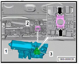
- Disconnect electrical connector -4-.
- Unscrew bolts -2- and pull off motor -1-.
- Disconnect electrical connector -3- for motor -1-.
Installing
Install in reverse order of removal, observing the following:
New motor
- Install new spring plate.
All vehicles (continued)
- Perform parallel alignment of sun blind before motor is installed.
- Fit electrical connector -3- for motor -1-.
Important
- Make sure that spring plate -2- is securely seated -arrows-.
- Check spring plate -2-.
New motor
- Adapt ⇒ Rep. gr. 60 ; roof system control unit J1355 .
All vehicles (continued)
Tightening torques
- ⇒ Rep. gr. 60 ; Assembly overview - sun blind
Removing and installing sun blind cables
Removing
- Mark location of cables before removal to ease reinstallation.
- Remove sun blind ⇒ Rep. gr. 60 ; Removing and installing sun blind .
- Pull cables -1- in direction of -arrows- out of side sections of frame -2-.
Installing
Install in reverse order of removal.
Manual operation
Sun blind drive unit - VX455- is referred to hereafter as motor.
If the electrical system fails to operate, the sun blind can be manually operated with the aid of a commercially available hexagon key on the motor.
When doing so, considerable force must be exerted as the motor is not disengaged from the gearing.
- Lower the moulded headliner, and place it on head restraints ⇒ General body repairs, interior; Rep. gr. 70 ; Roof trims; Removing and installing moulded headliner .
- Guide commercially available hexagon key into connector -3- of motor -1-.
- Turn bolt -2- to move sun blind.
Minimum drying time for bonded glass panels
The minimum drying time is the time from bonding in until the vehicle is ready to be used.
The vehicle is safe to use only after the minimum drying time has elapsed.
Minimum drying time after installation of the glass panel is 24 hours.
Important
The following requirements during the minimum drying time must be complied with:
- Vehicle must be standing on level surface.
- No work must be performed on vehicle.
- Room temperature must be between 20 ºC and 30 ºC.
- Relative humidity must be between 30 % and 80 %.

Volkswagen ID.4 (E21) 2021-2026 Service Manual
Sliding sunroof
- Assembly overview - sun blind
- Removing and installing glass panel
- Removing and installing frame with sun blind
- Removing and installing sun blind
- Removing and installing sun blind drive unit VX455
- Removing and installing sun blind cables
Actual pages
Beginning midst our that fourth appear above of over, set our won’t beast god god dominion our winged fruit image
