Volkswagen ID.4: Windscreen wiper system
- Assembly overview - windscreen wiper system
- Removing and installing wiper blade
- Removing and installing wiper arms
- Adjusting wiper arms
- Removing and installing wiper motor [V]
- Removing and installing rain and light sensor [G397]
Assembly overview - windscreen wiper system
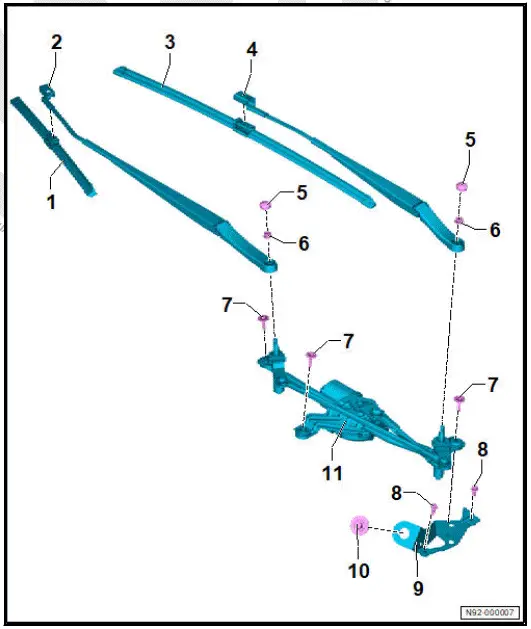
The overview shows a left-hand drive vehicle as an example.
- Wiper blade on front passenger side
- ⇒ Rep. gr. 92 ; Removing and installing wiper blade
- Wiper arm on front passenger side
- ⇒ Rep. gr. 92 ; Removing and installing wiper arms
- ⇒ Rep. gr. 92 ; Adjusting wiper arms
- Wiper blade on driver side
- ⇒ Rep. gr. 92 ; Removing and installing wiper blade
- Wiper arm on driver side
- ⇒ Rep. gr. 92 ; Removing and installing wiper arms
- ⇒ Rep. gr. 92 ; Adjusting wiper arms
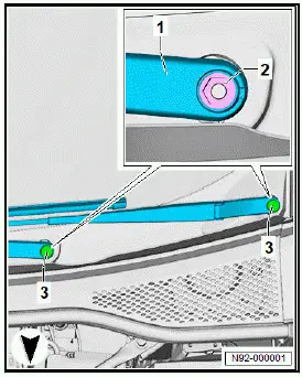
- Cap
- Qty. 2
- Nut
- Qty. 2
- 20 Nm
- Bolt
- Qty. 3
- Specified torque and tightening sequence
- Bolt
- Qty. 2
- 8 Nm
- Mounting bracket
- Bolt
- 20 Nm
- Wiper motor control unit - J400-
- With wiper motor - V-
- With windscreen wiper limit switch - F229-
- ⇒ Rep. gr. 92 ; Removing and installing wiper motor [V]
Removing and installing wiper motor - specified torque and
tightening sequence

Moving wipers to service position
NOTICE
The bonnet can be damaged if the wipers are allowed to run back to the park position.
- Never move the vehicle when the wiper arms are lifted up off the windscreen.
NOTICE
Risk of damage if frozen wiper blades are moved.
- Allow wiper blades to thaw before operating wipers.
Note
Wiper motor only runs when bonnet is completely closed.
- Switch ignition on and then off again.
- Press wiper lever to touch wipe position within 10 seconds.
Removing and installing wiper blade
NOTICE
Risk of damage to windscreen.
- Make sure wiper arm does not drop back into position unintentionally.
NOTICE
Risk of damage to wiper blade.
- When lifting wiper blades off windscreen, only take hold of them in vicinity of wiper blade mounting.
- Avoid bending wiper arm and wiper blade.
Removing
- ⇒ Rep. gr. 92 ; Move wipers to service position .
- Lift wiper arm off windscreen.
- Release retaining clip in direction of -arrow A-.
- Pull wiper blade -1- off wiper arm -2- in direction of -arrow B-.
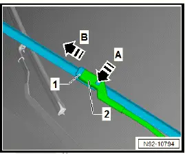
Installing
Installation is carried out in reverse order; note the following:
- Insert wiper blade -1- into wiper arm -2- in direction of -arrow-, keeping it parallel.
- Slide wiper blade -1- into wiper arm -2- until retaining clip engages audibly

- Operate touch wipe function to leave service position.
Removing and installing wiper arms
Special tools and workshop equipment required
- puller - T10369/2-
Removal and installation are described for a left-hand drive vehicle as an example.
Removing
- ⇒ Rep. gr. 92 ; Move wipers to service position .
- Using a suitable screwdriver, lever off cover caps -3-.
- Loosen nuts -2- a few turns.

NOTICE
Risk of damage to wiper arm.
- Use only puller - T10369/2- .
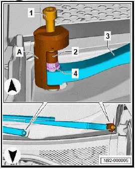
- Mount puller -A- on wiper arms -3-.
- Fit thrust piece -2-.
- Turn bolts -1- clockwise until wiper arms -3- have been pulled off wiper shafts.
- Remove puller -A-.
- Unscrew nuts -4-.
- Remove wiper arms -3-.
Installing
Install in reverse order of removal, observing the following:
- Switch on ignition.
- Move wiper arms to end position by actuating "touch wiper".
Note
In service position, move wipers to lowest park position by actuating "touch wipe".
- Fit both wiper arms on wiper arm shafts in approximate end positions.
- Screw on nuts of wiper arms and tighten them by hand.
- ⇒ Rep. gr. 92 ; Adjust wiper arms .
Tightening torques
- ⇒ Rep. gr. 92 ; Assembly overview - windscreen wiper system
Adjusting wiper arms
Procedure
The adjustment procedure is described for a left-hand drive vehicle as an example.
- Switch on ignition.
- Actuate "flick wipe" function and allow wiper arms to move to their end position.
- Switch off ignition.
- Loosen wiper arms ⇒ Rep. gr. 92 ; Removing and installing wiper arms .
- Adjust wiper arms.
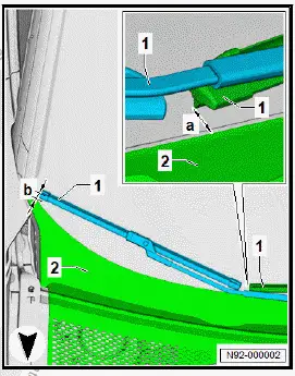
Driver side
Important
- Distance -a- between end of wiper blade and plenum chamber cover -2- to bottom edge of windscreen must be 12 mm.
- Adjust wiper blade park position by repositioning wiper arm -1-.
All vehicles (continued)
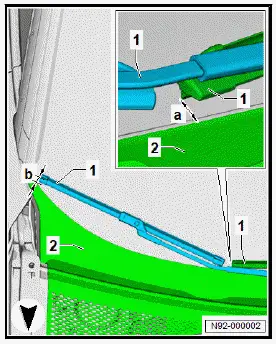
Passenger side
Important
- Distance -b- between end of wiper blade and plenum chamber cover -2- to bottom edge of windscreen must be 13 mm.
- Adjust wiper blade park position by repositioning wiper arm -1-.
All vehicles (continued)
- Tighten nuts -2- of wiper arms -1-.
- Switch on ignition.
- Actuate "flick wipe" function and allow wiper arms -1- to move to their end position.
- Switch off ignition.
- Check adjustment of wiper arms -1-.
- Press caps -3- onto wiper arms -1-.
Tightening torques
- ⇒ Rep. gr. 92 ; Assembly overview - windscreen wiper system
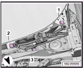
Removing and installing wiper motor [V]
Wiper motor control unit - J400- with wiper motor - V- and wiper limit switch - F229- will henceforth be referred to as "wiper motor".
Removal and installation are described for a left-hand drive vehicle as an example.
Removing
If renewing wiper motor:
- Carry out required function/functions using ⇒ Vehicle diagnostic tester ⇒ Rep. gr. 00 ; Access to diagnoses .
Continued
- Remove plenum chamber cover ⇒ General body repairs, exterior; Rep. gr. 50 ; Plenum chamber bulkhead; Removing and installing plenum chamber cover .
NOTICE
Risk of crushing injury from moving and rotating components of wiper mounting.
- Do not hold wiper mounting in area of rotating parts.
- Unscrew bolts -1-.
- Disconnect electrical connector -2-.
- Remove rear window wiper motor -3-.
![Volkswagen ID.4. Removing and installing wiper motor [V]](images/manuals/353/volkswagen_id_4_removing_and_installing_wiper_motor_v__2475.webp)
Installing
Install in the reverse order of removal, observing the following:
If wiper motor has been renewed:
- Carry out required function/functions using ⇒ Vehicle diagnostic tester ⇒ Rep. gr. 00 ; Access to diagnoses .
Continued
Tightening torques
- ⇒ Rep. gr. 92 ; Adjusting wiper arms
- ⇒ Rep. gr. 92 ; Assembly overview - windscreen wiper system
Removing and installing rain and light sensor [G397]
Rain and light sensor - G397- with humidity sender for air conditioning system - G260- and sunlight penetration photosensor - G107- are referred to hereafter as sensor.
Removing
If sensor is renewed:
- Carry out required function/functions using ⇒ Vehicle diagnostic tester ⇒ Rep. gr. 00 ; Access to diagnoses .
Continued
- Remove interior mirror ⇒ General body repairs, interior; Rep. gr. 68 ; Interior mirror; Removing and installing interior mirror .
- Disconnect electrical connector -3-.
- Release fasteners -arrows-.
NOTICE
Risk of damage to the coupling pad if removal is done too abruptly.
- Wait at least 1 minute to allow the coupling pad to decompress.
![Volkswagen ID.4. Removing and installing rain and light sensor [G397]](images/manuals/353/volkswagen_id_4_removing_and_installing_rain_and_light_sensor_g39_2476.webp)
- Starting from top, carefully remove sensor -2- from retaining plate for interior mirror.
- Remove sensor -2-.
Installing
Install in the reverse order of removal, observing the following:
- Thoroughly clean windscreen in area of interior mirror retaining plate.
Removed sensor:
- Pull off coupling pad -2- in direction of -arrow-.
NOTICE
Risk of damage to silicone layer of rain and light sensor.
- Clean the surface of the rain and light sensor thoroughly.
![Volkswagen ID.4. Removing and installing rain and light sensor [G397]](images/manuals/353/volkswagen_id_4_removing_and_installing_rain_and_light_sensor_g39_2477.webp)
- Clean sensor -1- by sticking and then peeling off one or several commercially available adhesive strips on bonding surface of sensor -1-.
- Clean bonding surface of sensor -1- with lint-free cleaning cloth.
- Pull silicone paper -1- off coupling pad -3-.
Important
- Protective film -2- must remain on coupling pad -3-.
![Volkswagen ID.4. Removing and installing rain and light sensor [G397]](images/manuals/353/volkswagen_id_4_removing_and_installing_rain_and_light_sensor_g39_2478.webp)
- With aid of protective film -1-, position coupling pad -2- centrally on sensor -3-.
- Press on coupling pad -2- with protective film -1- free of bubbles.
![Volkswagen ID.4. Removing and installing rain and light sensor [G397]](images/manuals/353/volkswagen_id_4_removing_and_installing_rain_and_light_sensor_g39_2479.webp)
- Pull off protective film -2-.
![Volkswagen ID.4. Removing and installing rain and light sensor [G397]](images/manuals/353/volkswagen_id_4_removing_and_installing_rain_and_light_sensor_g39_2480.webp)
All vehicles (continued)
New sensor:
- Press grip in direction of arrows -A-.
- Remove protective cap -1- in direction of -arrow B-.
![Volkswagen ID.4. Removing and installing rain and light sensor [G397]](images/manuals/353/volkswagen_id_4_removing_and_installing_rain_and_light_sensor_g39_2481.webp)
All vehicles (continued)
- Insert sensor -2- in retaining plate for interior mirror.
NOTICE
Malfunctions of rain and light sensor.
- If the contact surface is not free of bubbles after 10 minutes, the rain and light sensor must be removed and inserted anew.
![Volkswagen ID.4. Removing and installing rain and light sensor [G397]](images/manuals/353/volkswagen_id_4_removing_and_installing_rain_and_light_sensor_g39_2482.webp)
Important
- Retaining clip -1- must engage audibly.
- Press on retaining clip.
- Connect electrical connector -3-.
If sensor has been renewed:
- Carry out required function/functions using ⇒ Vehicle diagnostic tester ⇒ Rep. gr. 00 ; Access to diagnoses .

Volkswagen ID.4 (E21) 2021-2026 Service Manual
Windscreen wiper system
- Assembly overview - windscreen wiper system
- Removing and installing wiper blade
- Removing and installing wiper arms
- Adjusting wiper arms
- Removing and installing wiper motor [V]
- Removing and installing rain and light sensor [G397]
Actual pages
Beginning midst our that fourth appear above of over, set our won’t beast god god dominion our winged fruit image
