Volkswagen ID.4: Components/control units
- Removing and installing control unit for front display and information control panel [J685]
- Control unit 1 for information electronics [J794]
- Removing and installing front bass loudspeakers
- Removing and installing rear bass loudspeakers
- Removing and installing digital sound package control unit [J525]
- Removing and installing frequency modulation (FM) frequency filters [R178]/[R179]
- Removing and installing LTE aerial
- Removing and installing aerial amplifier for mobile telephone [R86]
- Removing and installing multifunction buttons [E440]/[E441]
- Removing and installing control unit for steering wheel contact detection [J1158]
- Removing and installing emergency call module control unit and communication unit [J949], rear bench seat
- Removing and installing loudspeaker for emergency call module [R335]
- Removing and installing emergency battery, telematics [A16]
Removing and installing control unit for front display and information control panel [J685]
Removing
The control unit 1 for information electronics - J794- will henceforth be referred to as "information electronics control unit".
Removal and installation are described for a left-hand drive vehicle as an example.
If the control unit for information electronics is renewed, perform the test plan for the renewal of the control unit:
- Carry out function "Renew control unit for information electronics" using ⇒ Vehicle diagnostic tester ⇒ Rep. gr. 00 ; Access to diagnoses .
Continued
- Remove glove compartment cover ⇒ General body repairs, interior; Rep. gr. 68 ; Compartments/covers; Removing and installing glove compartment cover .
- Release locking devices -arrows-, and pull out information electronics control unit -1- while at the same time swivelling it downwards.
- Disconnect electrical connectors.
![Volkswagen ID.4. Removing and installing control unit for front display and information control panel [J685]](images/manuals/353/volkswagen_id_4_control_panel_j685__1760.webp)
Installing
Install in the reverse order of removal, observing the following:
Important
- The information electronics control unit must engage audibly.
If the control unit for information electronics has been renewed, conclude the test plan for the renewal of the control unit:
- Conclude function "Renew control unit for information electronics" using ⇒ Vehicle diagnostic tester ⇒ Rep. gr. 00 ; Access to diagnoses .
Control unit 1 for information electronics [J794]
Removing
The bracket for the control unit 1 for information electronics - J794- will henceforth be referred to as "bracket".
Removal and installation are described for a left-hand drive vehicle as an example.
- Remove footwell vent on front passenger side ⇒ Heating, air conditioning; Rep. gr. 87 ; Air duct; Removing and installing footwell vent on front passenger side .
- Remove dash panel trim on front passenger side ⇒ General body repairs, interior; Rep. gr. 68 ; Compartments/covers; Removing and installing dash panel trim on front passenger side .
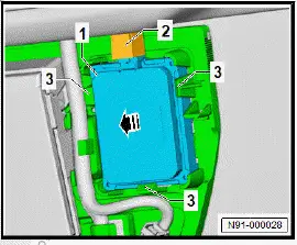
- Unscrew bolts -2- and -3-.
- Detach strut -1-.
![Volkswagen ID.4. Control unit 1 for information electronics [J794]](images/manuals/353/volkswagen_id_4_control_unit_1_for_information_electronics_j794__1761.webp)
- Remove control unit 1 for information electronics - J794- ⇒ Rep. gr. 91 ; Removing and installing control unit 1 for information electronics [J794] .
- Remove heater and air conditioning system control unit - J979- ⇒ Heating, air conditioning system; Rep. gr. 87 ; Other control components; Removing and installing heater and air conditioning system control unit [J979] .
- Remove data bus diagnostic interface - J533- ⇒ Electrical system; Rep. gr. 97 ; Control units; Removing and installing data bus diagnostic interface [J533] .
- Loosen fan for control unit - V274- , and lay it aside with
electrical wiring still connected ⇒ Electrical system; Rep.
gr. 97 ; Control units; Removing and installing fan for control unit [V274] .
- Pull out bracket -1- in direction of -arrow-, and detach it.
![Volkswagen ID.4. Control unit 1 for information electronics [J794]](images/manuals/353/volkswagen_id_4_control_unit_1_for_information_electronics_j794__1762.webp)
Installing
Install in the reverse order of removal, observing the following:
Tightening torques
- ⇒ General body repairs, interior; Rep. gr. 70 ; Central tube for dash panel; Assembly overview - central tube for dash panel
Removing and installing front treble loudspeakers [R20]/[R22]
Front left treble loudspeaker - R20- / front right treble loudspeaker - R22- are removed and installed together with upper A-pillar trim.
- Removing and installing upper A-pillar trim ⇒ General body repairs, interior; Rep. gr. 70 ; Trims, interior; Removing and installing upper A-pillar trim .
Removing and installing front bass loudspeakers
Special tools and workshop equipment required
- Drill, commercially available
- pop rivet pliers, commercially available
- suitable drill bit approx. 4 mm, commercially available
Removing
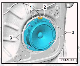
- Remove front door trim ⇒ General body repairs, interior; Rep. gr. 70 ; Front door trims; Removing and installing front door trim .
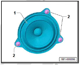
- Disconnect electrical connector -2-.
CAUTION
Risk of eye injuries due to metal swarf.
Eye irritation and injury possible.
- Put on safety goggles.
NOTICE
Corrosion damage due to swarf and damaged paintwork
- Completely remove swarf from the door, and immediately rectify any paintwork damage caused.
- Drill out pop rivets -3-, and remove loudspeaker -1-.
Installing
Install in the reverse order of removal, observing the following:
Important
- Only secure the loudspeaker using the specified pop rivets ⇒ Electronic parts catalogue (ETKA) .
Removing and installing rear bass loudspeakers
Special tools and workshop equipment required
- Drill, commercially available
- pop rivet pliers, commercially available
- suitable drill bit approx. 4 mm, commercially available
Removing
4-door models
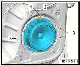
- Remove rear door trim ⇒ General body repairs, interior; Rep. gr. 70 ; Rear door trims; Removing and installing rear door trim .
All vehicles (continued)
2-door models
- Remove side trim ⇒ General body repairs, interior; Rep.
gr. 70 ; Trims, interior; Removing and installing side trim
All vehicles (continued)
- Disconnect electrical connector -2-.
CAUTION
Risk of eye injuries due to metal swarf.
Eye irritation and injury possible.
- Put on safety goggles.
NOTICE
Corrosion damage due to swarf and damaged paintwork
- Completely remove swarf from the door, and immediately rectify any paintwork damage caused.
- Drill out pop rivets -3-, and remove loudspeaker -1-.
Installing
Install in the reverse order of removal, observing the following:
Important
- Only secure the loudspeaker using the specified pop rivets ⇒ Electronic parts catalogue (ETKA) .
Removing and installing subwoofer [R211]
The subwoofer - R211- will henceforth be referred to as "subwoofer".
Removing
- Remove luggage compartment floor.
- Disconnect electrical connector -3-.
- Unscrew bolts -2-.
- Lift out subwoofer -1-.
![Volkswagen ID.4. Removing and installing subwoofer [R211]](images/manuals/353/volkswagen_id_4_removing_and_installing_rear_bass_loudspeakers_1765.webp)
Removing and installing digital sound package control unit [J525]
Removing
The digital sound package control unit - J525- will henceforth be referred to as "digital sound package control unit".
If the digital sound package control unit is renewed, perform the test plan for the renewal of the control unit:
- Carry out function "Renew digital sound package control unit" using ⇒ Vehicle diagnostic tester ⇒ Rep. gr. 00 ; Access to diagnoses .
Continued
- Remove left luggage compartment side trim ⇒ General body repairs, interior; Rep. gr. 70 ; Luggage compartment trims; Removing and installing luggage compartment side trim .
- Disconnect electrical connector -4-.
- Unscrew bolts -2-.
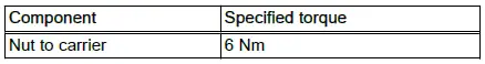
- Unscrew nuts -3-.
- Detach digital sound package control unit -1-.
![Volkswagen ID.4. Removing and installing digital sound package control unit [J525]](images/manuals/353/volkswagen_id_4_removing_and_installing_digital_sound_package_cont_1766.webp)
Installing
Install in the reverse order of removal, observing the following:
If the digital sound package control unit has been renewed, conclude the test plan for the renewal of the control unit:
- Conclude function "Renew digital sound package control unit" using ⇒ Vehicle diagnostic tester ⇒ Rep. gr. 00 ; Access to diagnoses .
Continued
Tightening torques
Removing and installing aerial module
Removing
The radio aerial 2 - R93- , aerial - R11- and digital radio aerial - R183- will henceforth be referred to as "aerial module".
Removal and installation are described for the left vehicle side as an example.
- Remove upper rear lid trim ⇒ General body repairs, interior; Rep. gr. 70 ; Luggage compartment trims; Removing and installing upper rear lid trim .
- Disconnect electrical connectors -arrows-.
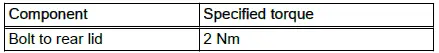
- Unscrew bolt -2-.
- Pull off aerial module -1- in direction of -arrow
Installing
Install in reverse order of removal, observing the following:
Tightening torques
Removing and installing frequency modulation (FM) frequency filters [R178]/[R179]
The frequency modulation (FM) frequency filter in negative wire - R178- and frequency modulation (FM) frequency filter in positive wire - R179- will henceforth be referred to as "frequency filter".
Removal and installation are described for the left side of vehicle as an example.
Removing
- Remove rear lid side trim ⇒ General body repairs, interior; Rep. gr. 70 ; Luggage compartment trims; Removing and installing rear lid side trim
- Disconnect electrical connectors -2-.
- Using commercially available plastic wedge, carefully lever out frequency filter -1-, and remove it.
![Volkswagen ID.4. Removing and installing frequency modulation (FM) frequency filters [R178]/[R179]](images/manuals/353/volkswagen_id_4__r178_r179__1770.webp)
Installing
Install in reverse order of removal.
Removing and installing roof aerial [RX5]
The roof aerial - RX5- will henceforth be referred to as "roof aerial".
Removing
- Remove internet access control unit - J666- ⇒ Rep. gr. 91 ; Removing and installing internet access control unit [J666] .
- Release retaining hooks -2-.
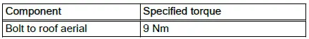
- Remove roof aerial -1- in direction of -arrow-.
![Volkswagen ID.4. Removing and installing roof aerial [RX5]](images/manuals/353/volkswagen_id_4__r178_r179__1771.webp)
Installing
Install in reverse order of removal.
Removing and installing LTE aerial
The LTE aerial 1 - R297- and LTE aerial 2 - R306- will henceforth be referred to as "LTE aerial".
Removing
- Remove bumper cover ⇒ General body repairs, exterior; Rep. gr. 63 ; Rear bumper; Removing and installing bumper cover .
- Disconnect electrical connector -2-.
- Unscrew nut -arrow-, and detach LTE aerial -1-.
Installing
Install in the reverse order of removal, observing the following:
Tightening torques
Removing and installing internet access control unit [J666]
The internet access control unit - J666- will henceforth be referred to as "internet access control unit".
Removing
Vehicles without sun blind
- Detach moulded headliner and place it on head restraints ⇒ General body repairs, interior; Rep. gr. 70 ; Roof trims; Removing and installing moulded headliner
All vehicles (continued)
Vehicles with sun blind
- Remove frame with sun blind ⇒ General body repairs, exterior; Rep. gr. 60 ; Sliding sunroof; Removing and installing frame with sun blind .
All vehicles (continued)
- Disconnect electrical connectors -3-, -4- and -6-.
- Loosen bolt -5-.
- Release locking device -2-, and detach internet access control unit -1-.
![Volkswagen ID.4. Removing and installing internet access control unit [J666]](images/manuals/353/volkswagen_id_4_removing_and_installing_lte_aerial_1774.webp)
Installing
Install in the reverse order of removal, observing the following:
Tightening torques
Removing and installing data transmission aerial
External vehicle communication aerial 2 - R394- and data transmission aerial - R180- will be referred to hereafter as "aerial".
Removing
- Remove bottom cover ⇒ General body repairs, interior; Rep. gr. 68 ; Interior mirror; Removing and installing interior mirror .
- Release locking devices -3-, and remove aerial -1- in direction of -arrow-.
- Disconnect electrical connector -2-.
Installing
Install in reverse order of removal.
Removing and installing aerial amplifier for mobile telephone [R86]
Removing
- Remove right luggage compartment side trim ⇒ General body repairs, interior; Rep. gr. 70 ; Luggage compartment trims; Removing and installing luggage compartment side trim .
- Unscrew bolts -2-, and remove seat trim bracket aerial amplifier for mobile telephone - R86- -1-.
- Disconnect electrical connectors -3-.
![Volkswagen ID.4. Removing and installing aerial amplifier for mobile telephone [R86]](images/manuals/353/volkswagen_id_4_removing_and_installing_aerial_amplifier_for_mobil_1777.webp)
Installing
Install in the reverse order of removal, observing the following:
Removing and installing charging unit 1 for mobile devices [J1146]
Charging unit 1 for mobile devices - J1146- is referred to hereafter as charging unit.
Removing
- Remove lining mat from centre console storage compartment.
NOTICE
Risk of damage to component surfaces when sharp-edged levers are used
- Mask off component in visible area using commercially available adhesive tape before using a levering tool.
- Release locking devices -2- and remove charging unit -1-.
- Disconnect electrical connector.
![Volkswagen ID.4. Removing and installing charging unit 1 for mobile devices [J1146]](images/manuals/353/volkswagen_id_4_removing_and_installing_aerial_amplifier_for_mobil_1778.webp)
Installing
Install in reverse order of removal.
Removing and installing multifunction buttons [E440]/[E441]
The left multifunction buttons in steering wheel - E440- with multifunction steering wheel control unit - J453- and right multifunction buttons in steering wheel - E441- will henceforth be referred to as "multifunction buttons".
Removing
If the multifunction buttons control unit is renewed, perform the test plan for the renewal of the control unit:
- Carry out function "Renew multifunction buttons" using ⇒ Vehicle diagnostic tester ⇒ Rep. gr. 00 ; Access to diagnoses .
Continued
- Remove airbag unit with airbag igniter on driver side [N95] ⇒ General body repairs, interior; Rep. gr. 69 ; Driver-side airbag; Removing and installing airbag unit with airbag igniter on driver side [N95] .
NOTICE
Risk of damage to the steering wheel.
- Mask off the steering wheel at the relevant locations to protect it from damage.
- Mask off steering wheel -1- with adhesive tape in areas indicated by -arrows-.
![Volkswagen ID.4. Removing and installing multifunction buttons [E440]/[E441]](images/manuals/353/volkswagen_id_4_removing_and_installing_multifunction_buttons_e44_1779.webp)
- Using commercially available plastic wedge -2-, unclip trim panel -1- in lower area -arrows-.
![Volkswagen ID.4. Removing and installing multifunction buttons [E440]/[E441]](images/manuals/353/volkswagen_id_4_removing_and_installing_multifunction_buttons_e44_1780.webp)
- Using commercially available plastic wedge -2-, unclip trim panel -1- successively in indicated areas (-arrows A- through -arrows C-).
- Detach trim -1- together with multifunction buttons -3-, -4- and lower trim -5-.
![Volkswagen ID.4. Removing and installing multifunction buttons [E440]/[E441]](images/manuals/353/volkswagen_id_4_removing_and_installing_multifunction_buttons_e44_1781.webp)
Vehicles with control unit for steering wheel contact detection - J1158-
- Disconnect electrical connector -1-.
![Volkswagen ID.4. Removing and installing multifunction buttons [E440]/[E441]](images/manuals/353/volkswagen_id_4_removing_and_installing_multifunction_buttons_e44_1782.webp)
Installing
Install in the reverse order of removal, observing the following:
- Clip in trim panel from below.
If the multifunction buttons control unit has been renewed, conclude the test plan for the renewal of the control unit:
- Conclude function "Renew multifunction unit control unit" using ⇒ Vehicle diagnostic tester ⇒ Rep. gr. 00 ; Access to diagnoses .
Continued
Tightening torques
- ⇒ Rep. gr. 91 ; Assembly overview - multifunction steering wheel
Removing and installing control unit for steering wheel contact detection [J1158]
The control unit for steering wheel contact detection - J1158- will henceforth be referred to as "control unit".
Removing
- Remove airbag unit with airbag igniter on driver side [N95] ⇒ General body repairs, interior; Rep. gr. 69 ; Driver side airbag; Removing and installing airbag unit with airbag igniter on driver side [N95] .
- Remove lower trim panel ⇒ Rep. gr. 91 ; Removing and installing multifunction buttons [E440]/[E441] .
- Disconnect electrical connectors -1- and -3-.
- Pull out control unit -2- in direction of -arrow-.
![Volkswagen ID.4. Removing and installing control unit for steering wheel contact detection [J1158]](images/manuals/353/volkswagen_id_4__j1158__1783.webp)
Installing
Install in reverse order of removal.
Removing and installing USB connection 1 [U41]
Removing
- Remove centre console ⇒ General body repairs, interior; Rep. gr. 68 ; Centre console; Removing and installing centre console .
- Release locking devices -1- and -2-, and pull out USB connection 1 - U41- .
![Volkswagen ID.4. Removing and installing USB connection 1 [U41]](images/manuals/353/volkswagen_id_4__j1158__1784.webp)
Installing
Install in the reverse order of removal, observing the following:
Important
- The USB connection 1 - U41- must be heard to engage.
Removing and installing USB charging socket 1 [U37]
Removing
- Remove rear centre console vent ⇒ General body repairs, interior; Rep. gr. 68 ; Centre console; Removing and installing rear centre console vent .
- Release locking devices -2-, and pull out USB charging socket 1 - U37- -1-.
![Volkswagen ID.4. Removing and installing USB charging socket 1 [U37]](images/manuals/353/volkswagen_id_4__j1158__1785.webp)
Installing
Install in the reverse order of removal, observing the following:
Important
- The USB charging socket 1 - U37- must be heard to engage.
Removing and installing emergency call module control unit and communication unit [J949], rear bench seat
Removing
Emergency call module control unit and communication unit - J949- is referred to hereafter as control unit.
If the control unit is renewed, perform the test plan for renewal of the control unit:
- Carry out function "Renew emergency call module control unit" using ⇒ Vehicle diagnostic tester ⇒ Rep. gr. 00 ; Access to diagnoses .
Continued
- Remove bench seat/individual seats ⇒ General body repairs, interior; Rep. gr. 72 ; Rear seat; Removing and installing bench seat / individual seats .
- Detach rear sill panel moulding ⇒ General body repairs, interior; Rep. gr. 70 ; Trims, interior; Removing and installing rear sill panel moulding .
- Lift up floor covering until control unit is accessible ⇒ General body repairs, interior; Rep. gr. 70 ; Interior trim; Removing and installing floor covering .
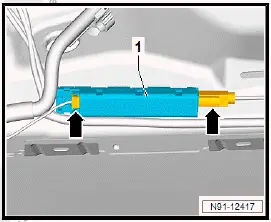
- Swivel out bracket -2- in direction of -arrow-.
![Volkswagen ID.4. Removing and installing emergency call module control unit and communication unit [J949], rear bench seat](images/manuals/353/volkswagen_id_4_communication_unit_j949_rear_bench_seat_1786.webp)
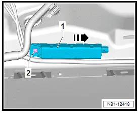
- Disconnect electrical connectors -1-.
![Volkswagen ID.4. Removing and installing emergency call module control unit and communication unit [J949], rear bench seat](images/manuals/353/volkswagen_id_4_communication_unit_j949_rear_bench_seat_1787.webp)
- Release locking devices -2-, and remove control unit -1-.
![Volkswagen ID.4. Removing and installing emergency call module control unit and communication unit [J949], rear bench seat](images/manuals/353/volkswagen_id_4_communication_unit_j949_rear_bench_seat_1788.webp)
Installing
Install in the reverse order of removal, observing the following:
Important
- Control unit must audibly engage in holder.
If the control unit has been renewed, conclude the test plan for the renewal of control unit:
Conclude function "Renew emergency call module control unit" using ⇒ Vehicle diagnostic tester ⇒ Rep. gr. 00 ; Access to diagnoses .
Removing and installing loudspeaker for emergency call module [R335]
Emergency call loudspeaker - R335- is referred to hereafter as loudspeaker.
Removing
Vehicles without control unit for head-up display - J898-
- Remove loudspeaker trim ⇒ General body repairs, interior; Rep. gr. 70 ; Dash panel; Removing and installing loudspeaker trim .
All vehicles (continued)
Vehicles with control unit for head-up display - J898-
- Remove cover for dash panel/head-up display ⇒ General body repairs, interior; Rep. gr. 70 ; Removing and installing cover for dash panel/head-up display .
All vehicles (continued)
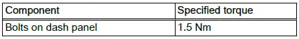
- Unscrew bolts -2-.
- Pull out loudspeaker -1-.
- Disconnect electrical connector.
Installing
Install in reverse order of removal, observing the following:
Tightening torques
Removing and installing emergency battery, telematics [A16]
The emergency battery, telematics - A16- will henceforth be referred to as "emergency battery".
Emergency call module control unit and communication unit - J949- is referred to hereafter as control unit.
Removing
If the emergency battery is renewed, perform the test plan for the renewal of the emergency battery.
- Carry out function "Renew emergency battery, telematics" using ⇒ Vehicle diagnostic tester ⇒ Rep. gr. 00 ; Access to diagnoses .
Continued
- Remove control unit ⇒ Rep. gr. 91 ; Removing and installing emergency call module control unit and communication unit [J949] .
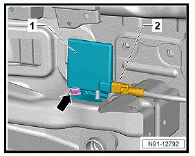
- Unscrew bolt -2-.
- Remove cover -1-.
![Volkswagen ID.4. Removing and installing emergency battery, telematics [A16]](images/manuals/353/volkswagen_id_4_removing_and_installing_emergency_battery_telemat_1791.webp)
- Disconnect connector -2-.
- Remove emergency battery -1-.
![Volkswagen ID.4. Removing and installing emergency battery, telematics [A16]](images/manuals/353/volkswagen_id_4_removing_and_installing_emergency_battery_telemat_1792.webp)
Installing
Install in the reverse order of removal, observing the following:
If the emergency battery was renewed, conclude the test plan for renewal of the emergency battery.
- Conclude function "Renew emergency battery, telematics" using ⇒ Vehicle diagnostic tester ⇒ Rep. gr. 00 ; Access to diagnoses .
Continued
Tightening torques

Volkswagen ID.4 (E21) 2021-2026 Service Manual
Components/control units
- Removing and installing control unit for front display and information control panel [J685]
- Control unit 1 for information electronics [J794]
- Removing and installing front bass loudspeakers
- Removing and installing rear bass loudspeakers
- Removing and installing digital sound package control unit [J525]
- Removing and installing frequency modulation (FM) frequency filters [R178]/[R179]
- Removing and installing LTE aerial
- Removing and installing aerial amplifier for mobile telephone [R86]
- Removing and installing multifunction buttons [E440]/[E441]
- Removing and installing control unit for steering wheel contact detection [J1158]
- Removing and installing emergency call module control unit and communication unit [J949], rear bench seat
- Removing and installing loudspeaker for emergency call module [R335]
- Removing and installing emergency battery, telematics [A16]
Actual pages
Beginning midst our that fourth appear above of over, set our won’t beast god god dominion our winged fruit image
