Volkswagen ID.4: A-pillar
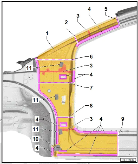
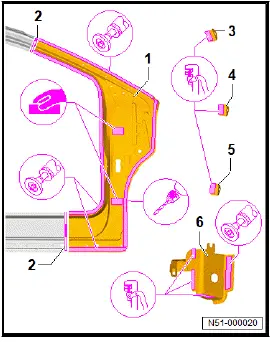
Assembly overview - A-pillar
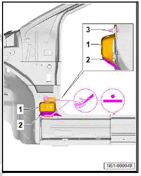
Overview shown for left side of vehicle as an example
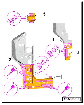
- A-pillar
- Subpart
- ⇒ Rep. gr. 51; Renewing A-pillar
- Separating cut
- Parting cut can be combined with others in cases where extent of damage requires multiple cuts.
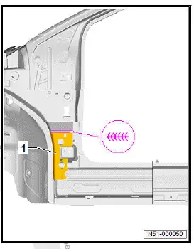
- Moulded foam inserts
- ⇒ Rep. gr. 00; Moulded foam inserts
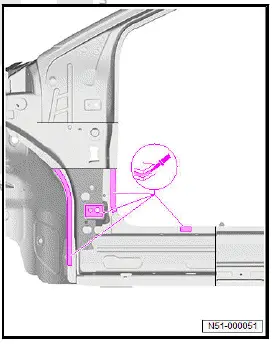
- Bonded area
- Separating cut
- Parting cut can be combined with others in cases where extent of damage requires multiple cuts.
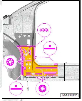
- Separating cut
- Parting cut can be combined with others in cases where extent of damage requires multiple cuts.
- Separating cut
- Parting cut can be combined with others in cases where extent of damage requires multiple cuts.
- Separating cut
- Parting cut can be combined with others in cases where extent of damage requires multiple cuts.
- Separating cut
- Observe replacement part blank
- End plate
- Lower wing bracket
- Wing bracket
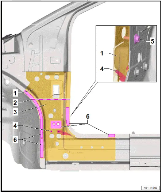
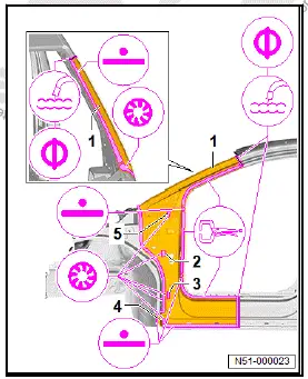
Assembly overview - A-pillar reinforcement
Overview shown for left side of vehicle as an example
- A-pillar reinforcement
- ⇒ Rep. gr. 51; Renewing A-pillar reinforcement, part section
- Separating cut
- Connecting piece
- Reinforcement on inside
- Moulded foam inserts
- ⇒ Rep. gr. 00; Moulded foam inserts
- Bolt
- (55 Nm)
- Bonded area
Renewing A-pillar
WARNING
Gases/vapours hazardous to health are generated when welding, soldering or cutting using tools which produce sparks in foam-treated areas.
- Do not weld, solder or cut closer than 15 mm to moulded foam inserts.
- Use an extraction system during work.
NOTICE
Do not damage underlying reinforcements.
Rewelding of reinforcement is not permitted due to safety reasons.
NOTICE
If welds are positioned too far on outside, strength could be impaired
- RP weld points must be placed as far as possible from outer edge of welding flange.
NOTICE
If adhesive is applied prematurely, bond could be impaired
- New part must be welded in within 90 minutes.
NOTICE
Bonding properties of adhesive may be impaired if adhesive components are not hardened sufficiently.
- After bonding, the vehicle must not be moved and left at room temperature (at least 15ºC) for 8 to 10 hours.
- During this time, the vehicle must be standing on a level surface.
Observe safety information ⇒ Rep. gr. 00; Safety information Only tools and workshop equipment authorised by Volkswagen AG may be used ⇒ 2.1 .
Removal and installation are described for left side of vehicle as an example.
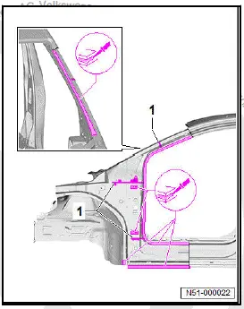
Removing
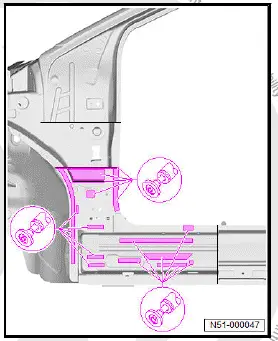
- Make separating cut -2- and -3- in a straight line, as shown in illustration.
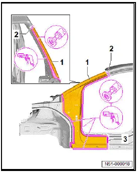
- Separate original joint.
- Remove A-pillar -1-.
- Remove any foam residue -1-.
- Remove remaining material.
- Completely remove remaining adhesive.
- Grind bonding surfaces and welding surfaces back to bare metal and clean.
Installing
Replacement parts
- For allocation of moulded foam inserts, see ⇒ Electronic parts catalogue (ETKA)
- For allocation of 2-pack body adhesive, see ⇒ Electronic parts catalogue (ETKA)
Important
- New parts must be adapted and attached with the vehicle standing on its wheels or straightening bracket set.
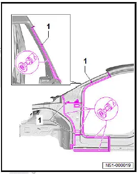
- Transfer separating cut -2- to new part -1-, and cut in a straight line.
- Grind welding surfaces and bonding surfaces on new part -1- and -6- down to bare metal and clean.
- Drill or - alternatively - punch holes of 8 mm in diameter for SG plug weld seam in new part -1- to -6-.
- Lightly sand bonding surfaces on new part -1- from inside.
- Prepare moulded foam inserts -1- for installation and insert.
- Apply 2-component body adhesive to entire surface.
- Adapt new part -1- to fit and fix in position.
- Check fit with add-on parts.
- Fix new part in position -1- with mole grips.
- Weld in new part -1-, RP spot weld seam and SG plug weld seam.
- Weld parting cuts (either MIG solder seam or SG stepped weld seam).
- Adjust new part -2- to -5- to fit and fix in position.
- Check fit with add-on parts.
- Weld in new part -2- to -5- (SG plug weld seam).
Renewing A-pillar reinforcement, part section
WARNING
Gases/vapours hazardous to health are generated when welding, soldering or cutting using tools which produce sparks in foam-treated areas.
- Do not weld, solder or cut closer than 15 mm to moulded foam inserts.
- Use an extraction system during work.
NOTICE
Do not damage underlying reinforcements.
Rewelding of reinforcement is not permitted due to safety reasons.
NOTICE
If welds are positioned too far on outside, strength could be impaired
- RP weld points must be placed as far as possible from outer edge of welding flange.
NOTICE
If adhesive is applied prematurely, bond could be impaired
- New part must be welded in within 90 minutes.
NOTICE
Bonding properties of adhesive may be impaired if adhesive components are not hardened sufficiently.
- After bonding, the vehicle must not be moved and left at room temperature (at least 15ºC) for 8 to 10 hours.
- During this time, the vehicle must be standing on a level surface.
Observe safety information ⇒ Rep. gr. 00; Safety information Only tools and workshop equipment authorised by Volkswagen AG may be used ⇒ 2.1 .
Removal and installation are described for left side of vehicle as an example.
Removing
A-pillar (part section) removed ⇒ Rep. gr. 51; Renewing A-pillar.
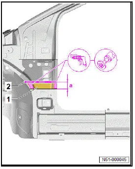
- Mark separating cut -2- according to dimension -a- and cut in a straight line.
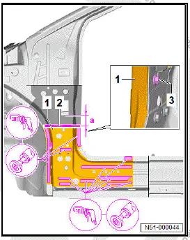
- Dimension -a- = 55 mm
- Separate original joint.
- Remove A-pillar reinforcement -1-.
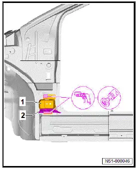
- Mark separating cut -2- according to dimension -a- and cut in a straight line.
- Dimension -a- = 40 mm
- Separate original joint.
- Remove remainder of A-pillar reinforcement -1-.
- Remove any foam residue -2-.
- Separate original joint.
- Remove remainder of hinge reinforcement -1-.
- Remove remaining material.
- Completely remove remaining adhesive.
- Grind bonding surfaces and welding surfaces back to bare metal and clean.
Installing
Replacement parts
- For allocation of moulded foam inserts, see ⇒ Electronic parts catalogue (ETKA)
- For allocation of 2-pack body adhesive, see ⇒ Electronic parts catalogue (ETKA)
Important
- New parts must be adapted and attached with the vehicle standing on its wheels or straightening bracket set.
- Transfer separating cut -2- to new part -1-, and cut in a straight line.
- Transfer separating cut -4- to new part -3-, and cut in a straight line.
- Transfer number and position of holes from removed section to new part -1-.
- Drill or alternately punch 8 mm diameter holes for SG plug weld seam.
- Grind welding surfaces and bonding surfaces on new part -1-, -3- and -5- down to bare metal and clean.
- Adapt new part -1- to fit and fix in position.
- Check fit with add-on parts.
- Apply 2-component body adhesive to entire surface.
- Weld in new part -1-, RP spot weld seam.
- Tighten bolt -3-.
- Prepare moulded foam inserts -1- for installation and insert.
- Adapt new part -1- to fit and fix in position.
- Check fit with add-on parts.
- Weld in new part -1-, SG continuous weld seam.
- Apply 2-component body adhesive to entire surface.
- Adapt new part -1- to fit and fix in position.
ID.4 2021 ➤ Body repairs - Edition 12.2022 114 Rep.
- Check fit with add-on parts.
- Weld in new part -1- (RP spot weld seam, SG plug weld seam and SG continuous weld seam).
- Install A-pillar part section ⇒ Rep. gr. 51; Renewing A-pillar
Tightening torques
- ⇒ Rep. gr. 51; Assembly overview - A-pillar reinforcement

Volkswagen ID.4 (E21) 2021-2026 Service Manual
A-pillar
Actual pages
Beginning midst our that fourth appear above of over, set our won’t beast god god dominion our winged fruit image
