Volkswagen ID.4: Bonnet
- Assembly overview - bonnet
- Assembly overview - Bowden cable
- Removing and installing bonnet
- Adjusting hinges
- Adjusting striker pin
- Adjusting bonnet lock
- Removing and installing striker pin
- Removing and installing Bowden cable
- Removing and installing bonnet stay
Assembly overview - bonnet
- Bonnet
- ⇒ Rep. gr. 55 ; Removing and installing bonnet
- ⇒ Rep. gr. 55 ; Adjusting bonnet
- Striker pin
- ⇒ Rep. gr. 55 ; Removing and installing striker pin
- ⇒ Rep. gr. 55 ; Adjusting striker pin
- Nut
- Qty. 2
- 9 Nm
- Adjusting buffer
- Qty. 4
- ⇒ Rep. gr. 55 ; Setting adjusting buffer
- Hinge
- ⇒ Rep. gr. 55 ; Removing and installing hinge
- ⇒ Rep. gr. 55 ; Adjusting hinges
- Nut
- Qty. 4
- 20 Nm
- Bolt
- Qty. 4
- 20 Nm
- Bonnet stay
- ⇒ Rep. gr. 55 ; Removing and installing bonnet stay
- Bonnet lock
- With bonnet contact switch - F266-
- ⇒ Rep. gr. 55 ; Removing and installing bonnet
- ⇒ Rep. gr. 55 ; Adjusting bonnet
- Bolt
- Qty. 2
- Renew after removing
- 12 Nm
- Rubber grommet for bonnet stay
- Retainer for bonnet stay
- Bolt
- Qty. 2
- 8 Nm
- Bolt
- Qty. 2
- 2 Nm
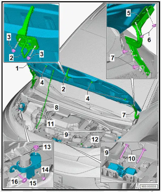
- Bonnet mounting
- Qty. 2
- Bolt
- Qty. 2
- 4.5 Nm
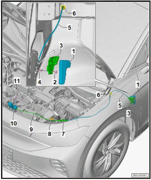
Assembly overview - Bowden cable
Overview shows a left-hand drive vehicle as an example
- Bonnet lock operating lever
- ⇒ Rep. gr. 55 ; Removing and installing bonnet lock operating lever
- Bolt
- 2 Nm
- Mounting bracket
- Expansion nut
- Bowden cable
- From mounting bracket -3- to Bowden cable coupling -7-
- ⇒ Rep. gr. 55 ; Removing and installing Bowden cable
- Grommet
- Bowden cable coupling
- Electrical connector for bonnet contact switch - F266-
- Bowden cable
- From Bowden cable coupling -7- to bonnet lock -10-.
- ⇒ Rep. gr. 55 ; Removing and installing Bowden cable
- Bonnet lock
- With bonnet contact switch - F266-
- ⇒ Rep. gr. 55 ; Removing and installing bonnet lock
- Bolt
- Qty. 2
- 12 Nm
Removing and installing bonnet
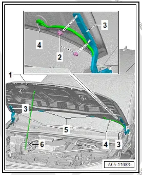
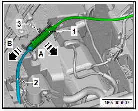
Removing
- Remove spray jets -5- ⇒ Electrical system; Rep. gr. 92 ; Window washer system; Removing and installing spray jets .
- Pull out washer fluid hose and electrical wires -4-.
- Loosen nuts -2- of hinges -3-.
Important
- A second person is required for the following steps.
- Unhook bonnet stay -6- from bonnet -1-.
- Unscrew nuts -2-.
- Remove bonnet -1-.
Installing
Install in reverse order of removal, observing the following:
NOTICE
Risk of damage to electrical wire if not installed straight.
- Do not kink electrical wire and route in a curve.
- Install washer fluid hose and electrical wires.
- ⇒ Rep. gr. 55 ; Adjust bonnet .
Tightening torques
- ⇒ Rep. gr. 55 ; Assembly overview - bonnet
Adjusting bonnet
Special tools and workshop equipment required
- setting gauge - 3371-
Important
- The vehicle must be standing on its wheels and on a level surface to ensure proper adjustment of the bonnet.
- Bonnet must engage in bonnet lock without excessive force.
- Striker pin must enter bonnet lock in centre.
The bonnet is correctly adjusted when the following applies in closed condition:
- Gaps are even
- Contours are flush with each other
- Bonnet does not protrude too far inwards or outwards
- Adjust adjusting buffers ⇒ Rep. gr. 55 ; Adjusting adjusting buffers .
- Adjust hinges ⇒ Rep. gr. 55 ; Adjusting hinges .
- Adjust bonnet lock ⇒ Rep. gr. 55 ; Adjusting bonnet lock .
- Adjust striker pin ⇒ Rep. gr. 55 ; Adjusting striker pin
- Check gaps with setting gauge - 3371- , observing ⇒ Rep. gr. 00 ; front gaps while doing so.
Adjusting hinges
Special tools and workshop equipment required
- setting gauge - 3371-
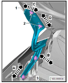
The procedure is described for the left side of vehicle as an example.
Note
The bonnet can be centred between the wings in direction of -arrow C- and in direction of -arrow D-.
- Loosen nuts -2- to adjust hinge -1- in direction of -arrow Cor in direction of -arrow D-.
Note
The height of the bonnet relative to the wings can be adjusted in direction of -arrow B-.
Note
The bonnet can be adjusted relative to the bumper cover in direction of -arrow A-.
- Loosen bolts -3- to adjust hinge -1- in direction of -arrow Aor in direction of -arrow B-.
- Verify gaps using setting gauge - 3371- . Observe ⇒ Rep. gr. 00 ; Gaps - front when doing this.
- Apply corrosion protection measures to hinges -1-, nuts -2- and bolts -3- ⇒ Corrosion protection on body, attachments and welded parts .
- ⇒ Rep. gr. 55 ; Adjust adjusting buffers .
Tightening torques
- ⇒ Rep. gr. 55 ; Assembly overview - bonnet
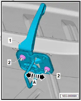
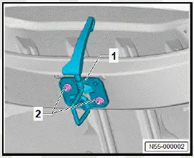
Adjusting striker pin
- Adjust striker pin in direction of -arrow A- to align it centrally relative to bonnet lock.
- Loosen nuts -2- to adjust striker pin -1- in direction of -arrow A-.
Important
- Do not use striker pin to align bonnet centrally in direction of -arrow A-.
- Striker pin must enter bonnet lock in centre
Tightening torques
- ⇒ Rep. gr. 55 ; Assembly overview - bonnet
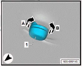
Setting adjusting buffers
Adjusting buffers stabilise the bonnet and provide shock absorption.
- Adjust bonnet lock ⇒ Rep. gr. 55 ; Removing and installing bonnet lock .
- Adjust striker pin ⇒ Rep. gr. 55 ; Adjusting striker pin .
Note
Adjusting buffers offer stability and protect against impact. Applying too much pressure on the rubber buffer will result in a malfunction.
- Turn adjusting buffer -1- in direction of -arrow A- or -arrow B-.
Important
- When bonnet is closed, adjusting buffers -1- must have light contact with stop buffers.
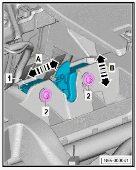
Adjusting bonnet lock
Special tools and workshop equipment required
- setting gauge - 3371-
Important
- Do not use bonnet lock to align bonnet centrally in direction of -arrow A-.
- Striker pin must enter bonnet lock in centre. ⇒ Rep. gr. 55 ; Adjusting striker pin
Note
The bonnet can be adjusted relative to the front bumper cover in direction of -arrow B-.
- Loosen bolts -2- to adjust bonnet lock -1- in direction of -arrow A- or direction of -arrow B-.
- Verify gaps using setting gauge - 3371- . Observe ⇒ Rep. gr. 00 ; Gaps - front when doing this.
- Apply corrosion protection measures to bolts -2- ⇒ Corrosion protection on body, attachments and welded parts .
Tightening torques
- ⇒ Rep. gr. 55 ; Assembly overview - bonnet
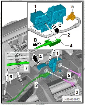
Removing and installing bonnet lock
Removal and installation are described for a left-hand drive vehicle as an example.
Removing
- Remove lock carrier ⇒ Rep. gr. 50 ; Removing and installing lock carrier .
- Unclip Bowden cable -2- and electrical wire -5- from retainers -7-.
- Unscrew bolts -3-.
- Remove bonnet lock -1- in direction of -arrow A- from lock carrier -6-.
- Unclip electrical wire -5- from bonnet lock.
- Slightly pull retainer -4- in direction of -arrow B- off bonnet lock -1-, and detach Bowden cable -2- in direction of -arrow C-.
Installing
Install in reverse order of removal, observing the following:
Tightening torques
- ⇒ Rep. gr. 55 ; Assembly overview - Bowden cable
Removing and installing striker pin
Removing
- Unscrew nuts -2-.
- Remove striker pin -1- from bonnet.
Installing
Install in reverse order of removal, observing the following:
- ⇒ Rep. gr. 55 ; Adjust striker pin .
Tightening torques
- ⇒ Rep. gr. 55 ; Assembly overview - bonnet
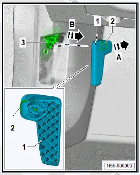
Removing and installing bonnet lock operating lever
Bonnet lock operating lever is referred to hereafter as operating lever.
Removal and installation are described for a left-hand drive vehicle as an example.
Removing
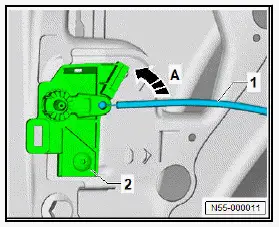
- Pull operating lever -1-, and hold it in this position.
- Using commercially available screwdriver, pull retaining clip -2- in direction of -arrow A- out of operating lever -1-.
- Detach operating lever -1- from mounting bracket -3- in direction of -arrow B-.
Installing
Install in reverse order.
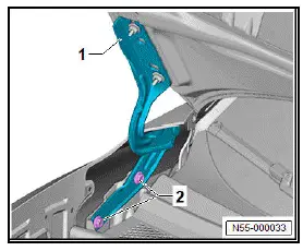
Removing and installing hinge
Removal and installation are described for the right vehicle side as an example.
Removing
- Remove bonnet ⇒ Rep. gr. 55 ; Removing and installing bonnet .
- Unscrew bolts -2-.
- Pull off hinge -1-.
Installing
Install in reverse order of removal, observing the following:
- Apply corrosion protection measures to bolts.
Observe instructions in the paintwork manual ⇒ Corrosion protection on body, attachments and welded parts .
- ⇒ Rep. gr. 55 ; Adjust bonnet .
Tightening torques
- ⇒ Rep. gr. 55 ; Assembly overview - bonnet
Removing and installing Bowden cable
Removal and installation are described for a left-hand drive vehicle as an example.
Removing
- Remove lower A-pillar trim ⇒ General body repairs, interior; Rep. gr. 70 ; Trims, interior; Removing and installing lower A-pillar trim .
- Remove footwell cover on driver side ⇒ General body repairs, interior; Rep. gr. 68 ; Compartments/covers; Removing and installing footwell cover on driver side .
- Remove front wheel housing liner on driver side ⇒ Rep. gr. 66 ; Removing and installing front wheel housing liner .
- Remove wiper motor - V- ⇒ Electrical system; Rep. gr. 92 ; Windscreen wiper system; Removing and installing wiper motor [V] .
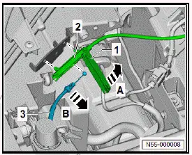
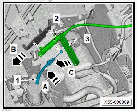
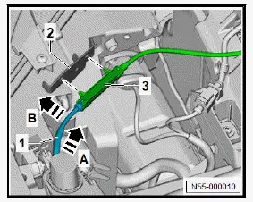
- Detach Bowden cable -1- in direction of -arrow A- from mounting bracket -2-.
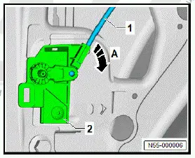
- Pull Bowden cable coupling -1- in direction of -arrow A- off carrier -3-.
- Pretension Bowden cable -2- in direction of -arrow B-, and hold it in this position.
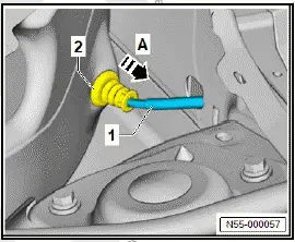
- Open cap -1- of Bowden cable coupling -2- in direction of -arrow A-.
- Remove Bowden cable -3- in direction of -arrow B- from Bowden cable coupling -2-.
- Pull Bowden cable -1- together with grommet -2- in direction of -arrow A- off body, and remove it.
Installing
- Guide Bowden cable -1- with grommet -2- in direction of -arrow A- through opening in body -3- towards vehicle interior.
- Push grommet -2- into opening in body -3-.
- Make sure that grommet -2- is seated correctly.
NOTICE
Risk of malfunction of the bonnet lock due to incorrect position of the Bowden cable in the Bowden cable coupling.
If the Bowden cable is installed in the wrong position, the bonnet can no longer be opened.
- Make sure that the Bowden cable is correctly positioned in the Bowden cable coupling.
- Always carry out a functional check before closing the bonnet.
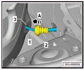
- Attach Bowden cable -1- in direction of -arrow A- to Bowden cable coupling -2-.
- Use cap -3- of Bowden cable coupling -2- to fix Bowden cable -1- in position, but do not close cap -3-.
- Pretension Bowden cable -1- in direction of -arrow B-, and hold it in this position.
- Close cap -3- in direction of -arrow C-.
- Relieve tension from Bowden cable -1- in direction of -arrow A-.
- Secure Bowden cable coupling -3- in direction of -arrow Bon carrier -2-.
- Attach Bowden cable -1- in direction of -arrow A- to mounting bracket -2-.
Further installation is carried out in reverse order of removal.
Observe the following when doing this:
- Perform functional check.
- Close bonnet.
Removing and installing bonnet stay
Special tools and workshop equipment required
- bonnet support - VAS 501 003-
Removal and installation are described for vehicles with bonnet stay on right as an example.
Bonnet stay mounting design is model-specific.
Removing
NOTICE
Risk of damage to adjacent components caused by a loose bonnet.
Risk of paint damage.
- Brace the bonnet open.
- Support bonnet using bonnet support - VAS 501 003- .
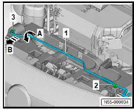
- Pull bonnet stay -1- out of clip -2-.
- Swivel bonnet stay -1- out of mounting on lock carrier.
- Remove bonnet stay -1- in direction of -arrow B-.
Installing
Install in reverse order.

Volkswagen ID.4 (E21) 2021-2026 Service Manual
Bonnet
- Assembly overview - bonnet
- Assembly overview - Bowden cable
- Removing and installing bonnet
- Adjusting hinges
- Adjusting striker pin
- Adjusting bonnet lock
- Removing and installing striker pin
- Removing and installing Bowden cable
- Removing and installing bonnet stay
Actual pages
Beginning midst our that fourth appear above of over, set our won’t beast god god dominion our winged fruit image
