Volkswagen ID.4: Rear lid
- Assembly overview - rear lid
- Assembly overview - rear lid power opening
- Removing and installing rear lid
- Adjusting rear lid
- Adjusting adjusting buffer at side
- Removing and installing power latching for rear lid [VX16]
- Removing and installing Bowden cable for power latching system
- Removing and installing rear lid handle
- Removing and installing adjusting buffer at bottom
- Removing and installing rear lid seal at roof channel
- Removing and installing gas strut
- Removing and installing rear lid drive unit [VX69]/[VX77]
- Removing and installing rear lid power opening senders [G750]/[G760]
- Removing and installing rear lid lock unit [VX25]
- Removing and installing rear lid power opening control unit [J938]
- Removing and installing hinge, double threaded connection
- Removing and installing rear lid control unit [J605]
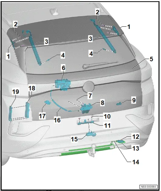
Assembly overview - rear lid
- Rear lid
- ⇒ Rep. gr. 55 ; Removing and installing rear lid
- ⇒ Rep. gr. 55 ; Adjusting rear lid
- Rear lid lock unit - VX25-
- ⇒ Rep. gr. 55 ; Removing and installing rear lid lock unit [VX25]
- Nut
- Qty. 2
- 20 Nm
- Bolt
- Qty. 4
- 2 Nm
- Adapter for rear lid handle
- ⇒ Rep. gr. 55 ; Removing and installing adapter for rear lid handle
- Rear lid handle
- With rear lid handle release button - E234-
- With reversing camera - R189- depending on equipment/installation period
- With rear overhead view camera - R246- depending on equipment/ installation period
- ⇒ Rep. gr. 55 ; Removing and installing rear lid handle
- Clip
- Qty. 4
- Expanding nut
- Qty. 4
- Bolt
- Qty. 2
- 8 Nm
- Stop for adjusting buffer
- ⇒ Rep. gr. 55 ; Removing and installing stop for adjusting buffer
- Lower adjusting buffer
- ⇒ Rep. gr. 55 ; Removing and installing adjusting buffer at bottom
- ⇒ Rep. gr. 55 ; Adjust adjustment buffer at bottom
- Hinge
- ⇒ Rep. gr. 55 ; Removing and installing hinge, double threaded connection
- Bolt
- Qty. 4
- 10 Nm
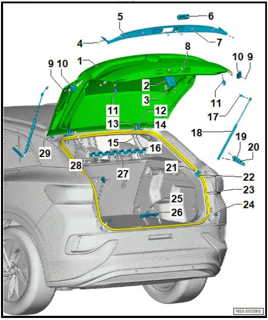
- Hinge seal
- Renew after removing
- Nut
- Qty. 2
- 8 Nm
- Nut
- Qty. 2
- Renew after removing
- Ball stud
- Qty. 2
- Renew after removing
- ⇒ Rep. gr. 55 ; Removing and installing ball stud
- 20 Nm +90º
- Gas strut
- Left and right
- Depending on equipment/version
- ⇒ Rep. gr. 55 ; Removing and installing gas strut
- ⇒ General information - body; Rep. gr. 52 ; Preparing for disposal; Preparing gas strut for disposal
- Mounting bracket
- Bolt
- Qty. 4
- Renew after removing
- 20 Nm +90º
- Bolt
- Qty. 2
- 8 Nm
- Adjusting buffer at side
- ⇒ Rep. gr. 55 ; Removing and installing adjusting buffer at side
- ⇒ Rep. gr. 55 ; Adjusting adjusting buffer at side
- Rear lid seal
- Renew after removing
- ⇒ Rep. gr. 55 ; Removing and installing rear lid seal
- Plug
- Left and right
- Nut
- Qty. 2
- 20 Nm
- Striker pin
- ⇒ Rep. gr. 55 ; Removing and installing striker pin
- ⇒ Rep. gr. 55 ; Adjusting striker pin
- Rear lid seal at roof channel
- ⇒ Rep. gr. 55 ; Removing and installing rear lid seal at roof channel
- Clip
- Qty. 8
- Plug
- Left and right
- Depending on equipment/version
Specified torque and tightening sequence
Assembly overview - rear lid power opening
- Mounting bracket
- Bolt
- Qty. 4
- Renew after removing
- 20 Nm +90º
- Rear lid drive unit - VX69- / rear lid drive unit 2 - VX77-
- Left: motor 1 for rear lid - V444- with sensor in motor 1 for rear lid - G745-
- Right: motor 2 for rear lid - V445- with sensor in motor 2 for rear lid - G746-
- ⇒ Rep. gr. 55 ; Removing and installing rear lid drive unit [VX69]/[VX77]
- ⇒ General information - body; Rep. gr. 52 ; Disposal preparations; Preparing rear lid drive unit [VX69]/ rear lid drive unit 2 [VX77] for disposal
- Ball stud
- Qty. 2
- Renew after removing
- ⇒ Rep. gr. 55 ; Removing and installing ball stud
- 20 Nm +90º
- Rear lid
- ⇒ Rep. gr. 55 ; Removing and installing rear lid
- ⇒ Rep. gr. 55 ; Adjusting rear lid
- Power latching for rear lid - VX16-
- With power latching motor for rear lid - V382-
- With power latching system limit switch, luggage compartment locked - F333-
- ⇒ Rep. gr. 55 ; Removing and installing power latching for rear lid [VX16]
- Nut
- Qty. 2
- 20 Nm
- Rear lid lock unit - VX25-
- Depending on equipment/installation version
- With rear lid contact switch - F111-
- With luggage compartment light switch - F5-
- With central locking rear lid lock unit - F327-
- ⇒ Rep. gr. 55 ; Removing and installing rear lid lock unit [VX25] with power latching system
- Operating unit for rear lid control - EX58-
- With rear lid closure button - E574-
- With button illumination bulb - L76-
- ⇒ Electrical system; Rep. gr. 96 ; Controls; Overview of fitting locations - controls in luggage compartment
- ⇒ Electrical system; Rep. gr. 96 ; Controls; Removing and installing operating unit for rear lid control [EX58]
- Nut
- Qty. 2
- 20 Nm
- Striker pin
- ⇒ Rep. gr. 55 ; Removing and installing striker pin
- ⇒ Rep. gr. 55 ; Adjusting striker pin
- Rear lid power opening control unit - J938-
- ⇒ Rep. gr. 55 ; Removing and installing rear lid power opening control unit [J938]
- Bracket for rear lid power opening control unit - J938-
- Renew after removing
- ⇒ Rep. gr. 55 ; Removing and installing holder for rear lid power opening control unit [J938]
- Rear lid power opening sender - G750- / rear lid power opening sender 2 - G760-
- Renew after removing
- ⇒ Rep. gr. 55 ; Removing and installing rear lid power opening senders [G750]/[G760]
- Rear lid handle - EX37-
- With rear lid handle release button - E234-
- ⇒ Rep. gr. 55 ; Removing and installing rear lid handle [EX37]
- Bowden cable
- For power latching for rear lid - VX16-
- Rear lid warning buzzer - H32-
- ⇒ Electrical system; Rep. gr. 96 ; Controls; Removing and installing rear lid warning buzzer [H32]
- Rear lid control unit - J605-
- ⇒ Rep. gr. 55 ; Removing and installing rear lid control unit [J605]
- Bracket for rear lid control unit - J605-
- ⇒ Rep. gr. 55 ; Removing and installing holder for rear lid control unit [J605]
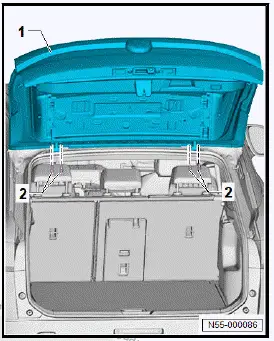
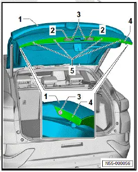
Removing and installing rear lid
Position of rubber grommet may vary depending on equipment/ version.
Depending on equipment/version, a drive unit is installed on the left side of the vehicle and a gas strut/concealed gas strut on the right side of the vehicle.
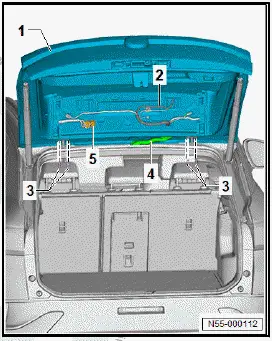
Removing
- Remove upper rear lid trim ⇒ General body repairs, interior; Rep. gr. 70 ; Luggage compartment trims; Removing and installing upper rear lid trim .
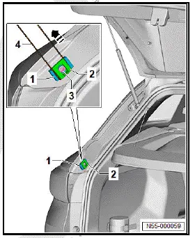
- Disconnect electrical connectors -5-.
- Release and pull off washer fluid hose -2-.
- Guide electrical wires and washer fluid hose -2- together with rubber grommet -4- out of rear lid -1-.
- Loosen bolts -3-.
Important
- The aid of an additional person is required for the subsequent work steps.
Vehicles with gas strut
- Remove gas struts ⇒ Rep. gr. 55 ; Removing and installing gas strut .
All vehicles (continued)
Vehicles with rear lid drive unit
- Remove rear lid drive unit ⇒ Rep. gr. 55 ; Rear lid; Removing and installing rear lid drive unit [VX69]/rear lid drive unit 2 [VX77] .
Vehicles with gas strut/concealed gas strut for rear lid on right side of vehicle
- Remove gas strut/concealed gas strut ⇒ Rep. gr. 55 ; Removing and installing gas strut .
All vehicles (continued)
- Unscrew bolts -2- and detach rear lid -1-.
Installing
Install in reverse order of removal, observing the following:
- Perform functional check of rear lid lock unit - VX25- .
- ⇒ Rep. gr. 55 ; Adjust rear lid .
Tightening torques
- ⇒ Rep. gr. 55 ; Assembly overview - rear lid
Adjusting rear lid
Special tools and workshop equipment required
- setting gauge - 3371-
Preparation
Important
- The vehicle must be standing on its wheels and on a level surface to ensure proper adjustment of the rear lid.
- The rear lid must engage in the striker pin without excessive force being applied.
The rear lid is correctly adjusted when the following applies in closed condition:
- The gaps are even.
- The contours are flush with each other.
- The rear lid does not protrude too far inwards or outwards.
The procedure is described for the left side of vehicle as an example.
- Loosen striker pin ⇒ Rep. gr. 55 ; Removing and installing striker pin .
Loosening hinge on rear lid
- Loosen bolts -2-.
- Push rear lid in direction of -arrow A- or -arrow B-.
- Tighten bolts -2- by hand.
- Tighten bolts -2- to specified torque
- Verify gaps using setting gauge - 3371- . Observe ⇒ Rep. gr. 00 ; Gaps - rear when doing this.
- If the rear lid is not properly adjusted, loosen hinge on body , and adjust rear lid.
Loosening hinge on body
- Remove C-pillar trim ⇒ General body repairs, interior; Rep. gr. 70 ; Trims, interior; Removing and installing C-pillar trim .
- Lower moulded headliner at rear ⇒ General body repairs, interior; Rep. gr. 70 ; Roof trims; Removing and installing moulded headliner .
- Loosen nuts -4- and -5-.
- Push rear lid in direction of -arrow A- or -arrow B-.
- Tighten nuts -4- and -5- by hand.
- Tighten nuts -4- and -5- to specified torque.
- Verify gaps using setting gauge - 3371- . Observe ⇒ Rep. gr. 00 ; Gaps - rear when doing this.
- Apply corrosion protection measures to hinges, nuts and bolts ⇒ Corrosion protection on body, attachments and welded parts .
Tightening torques
- ⇒ Rep. gr. 55 ; Assembly overview - rear lid
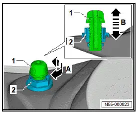
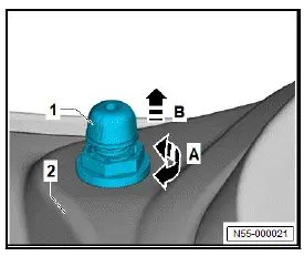
Adjust adjustment buffer at bottom
The procedure is described for the left side of vehicle as an example.
- Loosen striker pin ⇒ Rep. gr. 55 ; Removing and installing striker pin .
- Turn adjuster screw -1- in direction of -arrow A-.
Note
When doing this, the height of adjusting buffer -2- changes in direction of -arrow B-.
Important
- The rear lid must not protrude too far inwards or outwards in closed condition.
- Install striker pin ⇒ Rep. gr. 55 ; Removing and installing striker pin .
- Install striker pin ⇒ Rep. gr. 55 ; Removing and installing striker pin .
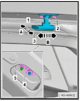
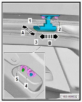
Adjusting adjusting buffer at side
The procedure is described for the left side of vehicle as an example.
- Loosen bolt -3- just far enough for adjusting buffer -2- to be shifted on mounting plate -1-.
- Fit commercially available cord -4- around adjusting buffer -2-.
- Close rear lid.
- Pull cord -4- to bring adjusting buffer -2- to stop against rear lid.
- Tighten bolt -3-.
Tightening torques
- ⇒ Rep. gr. 55 ; Assembly overview - rear lid
Adjusting striker pin
Special tools and workshop equipment required
- setting gauge - 3371-
- Remove lock carrier trim ⇒ General body repairs, interior; Rep. gr. 70 ; Luggage compartment trims; Removing and installing lock carrier trim .
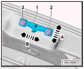
- Loosen nuts -2-.
- Move striker pin -1- to upper position, and push it in direction of -arrow A- or in direction of -arrow B-.
- Tighten nut -2- by hand.
Close rear lid.
Important
- Recess of rear lid lock unit - VX25- with rotary latch must be centred relative to striker pin when it engages.
- Check gaps with setting gauge - 3371- , observing ⇒ Rep.gr. 00 ; rear gaps while doing so.
Tightening torques
- ⇒ Rep. gr. 55 ; Assembly overview - rear lid
Removing and installing power latching for rear lid [VX16]
Power latching for rear lid - VX16- is referred to hereafter as power latching system.
The design and fitting location of the power latching system varies depending on equipment/version.
Removing
- Remove lower rear lid trim ⇒ General body repairs, interior; Rep. gr. 70 ; Luggage compartment trims; Removing and installing lower rear lid trim .
- Disconnect electrical connector -2-.
- To relieve load on Bowden cable -3-, turn mounting for Bowden cable -4- in direction of -arrow- and hold.
- Detach Bowden cable actuating mechanism -5-.
- Detach Bowden cable -3-.
![Volkswagen ID.4. Removing and installing power latching for rear lid [VX16]](images/manuals/353/volkswagen_id_4_removing_and_installing_power_latching_for_rear_li_1035.webp)
Vehicles with fastener for Bowden cable on power latching system
Vehicles with side fastener for Bowden cable on power latching system
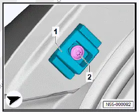
- Release fasteners in direction of -arrows-, and detach operating mechanism -2- from power latching for rear lid - VX16- .
![Volkswagen ID.4. Removing and installing power latching for rear lid [VX16]](images/manuals/353/volkswagen_id_4_removing_and_installing_power_latching_for_rear_li_1036.webp)
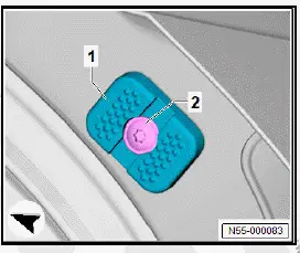
Continued Vehicles with fastener for Bowden cable on power latching system
Vehicles with reversed fastener for Bowden cable on power latching system
- Continued Vehicles with fastener for Bowden cable on power latching system Vehicles with reversed fastener for Bowden cable on power latching system
![Volkswagen ID.4. Removing and installing power latching for rear lid [VX16]](images/manuals/353/volkswagen_id_4_removing_and_installing_power_latching_for_rear_li_1037.webp)
All vehicles (continued)
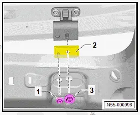
- Remove Bowden cable.
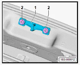
- To release clips -1-, turn clip -1- 90º in direction of -arrow-.
- Remove power latching system -2-.
![Volkswagen ID.4. Removing and installing power latching for rear lid [VX16]](images/manuals/353/volkswagen_id_4_removing_and_installing_power_latching_for_rear_li_1038.webp)
Installing
Install in reverse order of removal, observing the following:
- Perform functional check with rear lid open.
Removing and installing Bowden cable for power latching system
The Bowden cable for power latching system will henceforth be referred to as "Bowden cable".
Removing
- Remove lower rear lid trim ⇒ General body repairs, interior; Rep. gr. 70 ; Luggage compartment trims; Removing and installing lower rear lid trim .
- Pull off cover for rear lid lock unit - VX25- -1- in direction of -arrow A-.
- Open Bowden cable securing cap -2- in direction of -arrow B-.
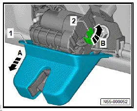
- Turn Bowden cable at lever -3- 90º in direction of -arrow A-, and detach it from rear lid lock unit - VX25- -2-.
- Press and hold operating lever -5- as far as stop in direction of -arrow B- using commercially available screwdriver -1-.
- Detach Bowden cable -4- in direction of -arrow C- from operating lever -5-, and remove Bowden cable.

- Release fasteners in direction of -arrows-, and detach support bracket -4- from power latching for rear lid - VX16- .
- Detach ball head of Bowden cable -3- from operating mechanism -2-.
- Detach Bowden cable -1-.

Installing
Install in reverse order.
Removing and installing rear lid handle
Fitting location of rear lid handle varies slightly depending on equipment/version
Removing
- Remove lower rear lid trim ⇒ General body repairs, interior; Rep. gr. 70 ; Luggage compartment trims; Removing and installing lower rear lid trim .
Vehicles with reversing camera - R189-
- Disconnect electrical connector for reversing camera - R189- ⇒ Driver assist systems; Rep. gr. 98 ; Senders/sensors/ control units; Removing and installing reversing camera [R189] .
- Disconnect washer fluid hose from spray jet for reversing camera - R189- .
All vehicles (continued)
Vehicles with rear overhead view camera - R246-
- Disconnect electrical connector for rear overhead view camera - R246- ⇒ Driver assist systems; Rep. gr. 98 ; Senders/ sensors/control units; Removing and installing rear overhead view camera [R246] .
All vehicles (continued)
- Disconnect electrical connector -2-.
- Release locking devices -arrows-, and remove rear lid handle -1- from outside in direction of -arrow A-.
Installing
Install in reverse order of removal, observing the following:
Vehicles with reversing camera - R189-
- ⇒ Driver assist systems; Rep. gr. 98 ; Reversing camera; Calibrating reversing camera [R189] .
All vehicles (continued)
Vehicles with rear overhead view camera - R246-
- ⇒ Driver assist systems; Rep. gr. 98 ; Overhead view camera; Calibrating overhead view camera system .
All vehicles (continued)
- Perform functional check with rear lid open.
Removing and installing adapter for rear lid handle
Removing
- Remove rear lid handle ⇒ Rep. gr. 55 ; Removing and installing rear lid handle .
- Unscrew bolts -3-.
- Unclip trim -5- using commercially available plastic wedge.
- Disconnect electrical connectors for left number plate light - X4- -2- and right number plate light - X5- -2-.
- Detach adapter for rear lid handle -4- from rear lid -1-.
Installing
Install in reverse order.
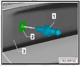
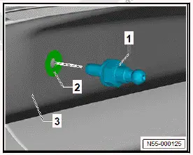
Removing and installing adjusting buffer at bottom
Removing
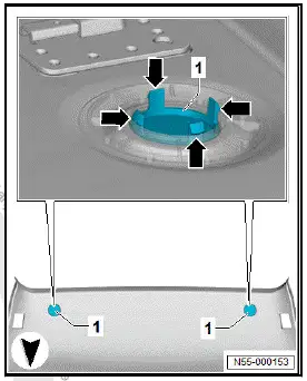
- Turn lower adjusting buffer -1- 90º in direction of -arrow A-.
- Remove lower adjusting buffer -1- in direction of -arrow B-.
Installing
Install in reverse order of removal, observing the following:
- ⇒ Rep. gr. 55 ; Adjust lower adjusting buffer .
Removing and installing adjusting buffer at side
Removal and installation are described for the left vehicle side as an example.
Removing
- Unscrew bolt -2-.
- Detach adjusting buffer at side -1-.
Installing
Install in reverse order of removal, observing the following:
- ⇒ Rep. gr. 55 ; Adjusting adjusting buffer at side .
Removing and installing stop for adjusting buffer
Removal and installation are described for the left vehicle side as an example.
Removing
- Unscrew bolt -2-.
- Detach stop for adjusting buffer -1-.
Installing
Install in reverse order of removal, observing the following:
Tightening torques
- ⇒ Rep. gr. 55 ; Assembly overview - rear lid
Removing and installing striker pin
Removing
- Remove lock carrier trim ⇒ General body repairs, interior; Rep. gr. 70 ; Luggage compartment trims; Removing and installing lock carrier trim .
- Unscrew nuts -2-.
- Remove striker pin -1-.
Installing
Install in reverse order of removal, observing the following:
- ⇒ Rep. gr. 55 ; Adjust striker pin .
Tightening torques
- ⇒ Rep. gr. 55 ; Assembly overview - rear lid
Removing and installing rear lid seal at roof channel
Removing and installing rear lid seal
Removing
- Unclip trim -2- using commercially available plastic wedge.
- Detach rear lid trim at roof channel -1- from rear lid -3-.

Installing
Install in reverse order of removal, observing the following:
- Fit rear lid seal at roof channel so that clips can be heard to engage.
Removing and installing rear lid seal
Removing
- Pull rear lid seal -1- off body flange -2-.

Installing
NOTICE
When the rear lid seal is pulled off, the flanks of the seal can be bent up, so that the rear lid seal no longer provides the required sealing function at some points.
Water ingress or wind noise may result.
- If the rear lid seal has been pulled off only partially, compress the seal flanks, and install the rear lid seal.
- Make sure that adjacent trims are located in the beading of the rear lid seal.
- Align vulcanised point of rear lid seal -1- with striker pin -arrows-.
- Press rear lid seal -1- evenly onto body flange -2- by hand.

Removing and installing gas strut
Special tools and workshop equipment required
- bonnet support - VAS 501 003-
Removal and installation are described for left side of vehicle as an example.
Removing
Important
- Make sure that rear lid is seated securely.
- Support rear lid using bonnet support - VAS 501 003- .
NOTICE
Risk of damage to spring clip caused by levering it out too far.
The spring clip may break.
- Never lever spring clip out of ball socket.
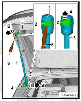
- Position commercially available screwdriver -6- under spring clip -2-.
- Lift spring clip -2- in direction of -arrow A- over ball socket -3-.
- Pull gas strut -1- in direction of -arrow B- off ball stud -5-.
- Press back spring clip -2- into initial position.
- Repeat procedure for 2nd spring clip -2-.
- Pull gas strut -1- in direction of -arrow B- off ball-head pin -4-.
Installing
Install in reverse order of removal, observing the following:
Important
- Spring clips must be pushed on until they are heard to engage.
- Make sure that gas strut is seated securely.
If "gas strut" is renewed
- ⇒ General information - body; Rep. gr. 52 ; Preparing for disposal; Preparing gas strut for disposal
All vehicles (continued)
If "gas strut with trim" is renewed
- ⇒ General information - body; Rep. gr. 52 ; Preparing for disposal; Preparing covered gas strut for disposal
Removing and installing rear lid drive unit [VX69]/[VX77]
Special tools and workshop equipment required
- bonnet support - VAS 501 003-
Rear lid drive unit - VX69- and rear lid drive unit 2 - VX77- are referred to hereafter as drive unit.
Removal and installation are described for left side of vehicle as an example.
Removing
NOTICE
Risk of damage to adjacent components due to loose rear lid.
Risk of paint damage.
- Support rear lid.
- Support rear lid using bonnet support - VAS 501 003- .
Important
- Make sure that rear lid is seated securely.
- Remove C-pillar trim ⇒ General body repairs, interior; Rep. gr. 70 ; Trims, interior; Removing and installing C-pillar trim .
- Disconnect electrical connector -3-.
- Remove grommet -2-, and guide out electrical wire -4-.
![Volkswagen ID.4. Removing and installing rear lid drive unit [VX69]/[VX77]](images/manuals/353/volkswagen_id_4_removing_and_installing_rear_lid_drive_unit_vx69__1052.webp)
- Push drive unit -1- onto ball-head pin -5-, and hold it in this position.
NOTICE
Risk of damage to spring clip caused by levering it out too far.
The spring clip may break.
- Never lever spring clip completely out of ball socket.
- Lever off spring clip -3- in direction of -arrow- using commercially available screwdriver -4-.
- Pull ball socket of drive unit -1- off ball-head pin -5-.
- Press back spring clip -3- into initial position.
- Repeat procedure for 2nd spring clip.
![Volkswagen ID.4. Removing and installing rear lid drive unit [VX69]/[VX77]](images/manuals/353/volkswagen_id_4_removing_and_installing_rear_lid_drive_unit_vx69__1053.webp)
If drive unit needs to be renewed:
- ⇒ General information - body; Rep. gr. 52 ; Preparing for disposal; Preparing drive unit for rear lid [VX69]/drive unit 2 for rear lid [VX77] for disposal .
All vehicles (continued)
Installing
Install in reverse order of removal, observing the following:
Important
- Spring clips must be pushed on until they are heard to engage.
- Make sure that gas strut is seated securely.
Removing and installing rear lid power opening senders [G750]/[G760]
Special tools and workshop equipment required
- hot air blower - V.A.G 1416-
- roller - T40400-
Rear lid power opening sender - G750- and rear lid power opening sender 2 - G760- are referred to hereafter as rear lid power opening sender.
Important
- Observe specifications with regard to temperature, cleaning and removal of adhesive residue ⇒ General information - body; Rep. gr. 52 ; Self-adhesive components; Specifications for self-adhesive components .
Removing
- Remove bumper cover ⇒ Rep. gr. 63 ; Removing and installing bumper cover .
- Disconnect electrical connector -1-.
- Heat up rear lid power opening sender -2- in area of adhesive tape -3- using hot air blower - V.A.G 1416- ⇒ General information - body; Rep. gr. 52 ; Self-adhesive components; Specifications for self-adhesive components .
- Pull off rear lid power opening sender -2-.
![Volkswagen ID.4. Removing and installing rear lid power opening senders [G750]/[G760]](images/manuals/353/volkswagen_id_4_removing_and_installing_rear_lid_power_opening_sen_1054.webp)
Installing
Install in reverse order of removal, observing the following:
- Remove adhesive residue and clean bonding surfaces ⇒ General information - body; Rep. gr. 52 ; Self-adhesive components; Specifications for self-adhesive components .
- Pull off protective film from adhesive tape.
- Position rear lid power opening sender -1- at marked areas -2- and press into place.
- Press rear lid power opening sender -1- in area of adhesive tape with a force 65 N using roller - T40400- .
Important
- Observe minimum drying time of 30 minutes.
![Volkswagen ID.4. Removing and installing rear lid power opening senders [G750]/[G760]](images/manuals/353/volkswagen_id_4_removing_and_installing_rear_lid_power_opening_sen_1055.webp)
Removing and installing rear lid lock unit [VX25]
Rear lid lock unit - VX25- is referred to hereafter as lock unit.
Removing
- Remove lower rear lid trim ⇒ General body repairs, interior; Rep. gr. 70 ; Luggage compartment trims; Removing and installing lower rear lid trim .
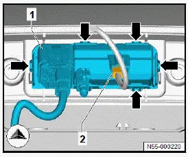
- Pull off lock unit cover -4- in direction of -arrow A-.
- Disconnect electrical connector -2-.
- Unscrew nuts -3-.
- Pull lock unit -1- in direction of -arrow B- off stud -6-. When doing this, the locking device -5- will be released.
![Volkswagen ID.4. Removing and installing rear lid lock unit [VX25]](images/manuals/353/volkswagen_id_4_removing_and_installing_rear_lid_lock_unit_vx25__1056.webp)
Installing
Install in reverse order of removal, observing the following:
- Perform functional check with rear lid open.
Tightening torques
- ⇒ Rep. gr. 55 ; Assembly overview - rear lid
Removing and installing rear lid lockunit [VX 25]
Rear lid lock unit - VX25- is referred to hereafter as lock unit.
Removing
Rear lid lock unit [VX25] with power latching system
- Disengage Bowden cable ⇒ Rep. gr. 55 ; Removing and installing Bowden cable for power latching system .
All vehicles (continued)
Rear lid lock unit [VX25] without power latching system
- Remove lower rear lid trim ⇒ General body repairs, interior; Rep. gr. 70 ; Luggage compartment trims; Removing and installing lower rear lid trim .
All vehicles (continued)
- Disconnect electrical connector -3-.
- Unscrew nuts -2-.
- Pull lock unit -1- in direction of -arrow A- off stud -4-.
![Volkswagen ID.4. Removing and installing rear lid lockunit [VX 25]](images/manuals/353/volkswagen_id_4_removing_and_installing_rear_lid_lock_unit_vx25__1057.webp)
Installing
Install in reverse order of removal, observing the following:
- Perform functional check with tailgate open.
Tightening torques
- ⇒ Rep. gr. 55 ; Assembly overview - rear lid power opening
Removing and installing rear lid power opening control unit [J938]
Rear lid power opening control unit - J938- is referred to hereafter as control unit.
Removing
- Remove bumper cover ⇒ Rep. gr. 63 ; Removing and installing bumper cover .
- Disconnect electrical connectors -2- and -3-.
- Release fasteners in direction of -arrow-.
- Detach control unit -1- from control unit holder -4-.
![Volkswagen ID.4. Removing and installing rear lid power opening control unit [J938]](images/manuals/353/volkswagen_id_4_removing_and_installing_rear_lid_power_opening_con_1058.webp)
Installing
Install in reverse order.
Removing and installing holder for rear lid power opening control unit [J938]
Holder for rear lid power opening control unit - J938- is referred to hereafter as holder.
Important
- Instructions and specifications regarding temperature, minimum drying time, removal of adhesive residue and cleaning must be adhered to ⇒ General information - body; Rep. gr. 52 ; Self-adhesive components; Specifications for selfadhesive components .
Removing
- Remove rear lid power opening control unit - J938- ⇒ Rep. gr. 55 ; Removing and installing rear lid power opening control unit [J938] .
- Apply heat to holder -1- in area of adhesive tape -2-.
- Pull off holder -1-.
![Volkswagen ID.4. Removing and installing holder for rear lid power opening control unit [J938]](images/manuals/353/volkswagen_id_4_removing_and_installing_rear_lid_power_opening_con_1059.webp)
Installing
Install in reverse order of removal, observing the following:
- Remove adhesive residue, and clean bonding surfaces.
- Pull protective backing off adhesive tape -2-.
- Place holder -1- in marked area -3- and press on.
Important
- The minimum drying time must be adhered to.
![Volkswagen ID.4. Removing and installing holder for rear lid power opening control unit [J938]](images/manuals/353/volkswagen_id_4_removing_and_installing_rear_lid_power_opening_con_1060.webp)
Removing and installing hinge, double threaded connection
Removing
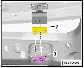
Vehicles with plugs on moulded headliner
- Detach locking devices -arrows- of plugs -1- using commercially available removal wedge.
- Remove plug -1-.
All vehicles (continued)
Vehicles without roof end strip and without plugs in moulded headliner
- Remove C-pillar trim ⇒ General body repairs, interior; Rep. gr. 70 ; Trims, interior; Removing and installing C-pillar trim
NOTICE
Risk of damage to the moulded headliner if the moulded headliner is not lowered far enough.
- Make sure to lower the moulded headliner far enough.
- Lower moulded headliner enough so that nuts of hinge can be unscrewed without damaging moulded headliner ⇒ General body repairs, interior; Rep. gr. 70 ; Roof trim; Removing and installing moulded headliner .
All vehicles (continued)
Important
- Gas struts or motor 1 for rear lid - V444- and motor 2 for rear lid - V445- must remain installed.
Important
- The aid of an additional person is required for the subsequent work steps.
- Have a second person hold rear lid in position in lower area -arrow- at side of hinge to be removed.
NOTICE
Risk of damage to paint due to loose rear lid.
- Cover the roof channel and upper edge of the rear lid with commercially available adhesive tape.
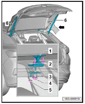
- Loosen nuts -4- and -5- and bolts -2-.
- Unscrew nuts -4- and -5-.
- Remove seal -3-.
- Unscrew bolts -2-.
- Pull out hinge -1-.
Installing
Install in reverse order of removal, observing the following:
- Tighten nuts -1- and -3-.
- Loosen nut -3-.
- Tighten nut -3- until gasket -2- is properly seated.
- Apply corrosion protection measures to nuts and bolts.
Observe instructions in the paintwork manual ⇒ Corrosion protection on body, attachments and welded parts .
- ⇒ Rep. gr. 55 ; Adjust rear lid .
Tightening torques
- ⇒ Rep. gr. 55 ; Assembly overview - rear lid
Removing and installing ball stud
Removing
- Remove gas strut ⇒ Rep. gr. 55 ; Removing and installing gas strut .
- Unscrew ball stud -1-.
Installing
Install in reverse order of removal, observing the following:
- Sand down contact surfaces of ball stud -2- to bare metal before installing.
Important
- Apply paint to ball stud and contact surfaces as specified in ⇒ Paint manual after installing.
Tightening torques
- ⇒ Rep. gr. 55 ; Assembly overview - rear lid
Removing and installing rear lid control unit [J605]
Removing
Rear lid control unit - J605- is referred to hereafter as control unit.
- Remove left luggage compartment side trim ⇒ General body repairs, interior; Rep. gr. 70 ; Luggage compartment trims; Removing and installing luggage compartment side trim .
Models without bracket for control unit
- Disconnect electrical connectors -2-.
- Release locking devices -3- in direction of -arrow A-, and push control unit -1- to stop in direction of -arrow B-.
- Remove control unit -1- in direction of -arrow C-.

All vehicles (continued)
Models with bracket for control unit
- Disconnect electrical connectors -2-.
- Release locking devices -3- in direction of -arrow A-, and push control unit -1- to stop in direction of -arrow B-.
- Detach control unit -1- in direction of -arrow C- from control unit holder -4-.

All vehicles (continued)
Installing
Install in reverse order.
Removing and installing holder for rear lid control unit [J605]
The holder for the rear lid control unit - J605- will henceforth be referred to as "holder".
Removing
- Detach rear lid control unit - J605- , and lay it aside with electrical wires connected ⇒ Rep. gr. 55 ; Removing and installing rear lid control unit [J605] .
- Release locking device -2- in direction of -arrow A-, and remove holder -1- in direction of -arrow B-.
![Volkswagen ID.4. Removing and installing holder for rear lid control unit [J605]](images/manuals/353/volkswagen_id_4_removing_and_installing_rear_lid_control_unit_j60_1068.webp)
Installing
Install in reverse sequence of removal.

Volkswagen ID.4 (E21) 2021-2026 Service Manual
Rear lid
- Assembly overview - rear lid
- Assembly overview - rear lid power opening
- Removing and installing rear lid
- Adjusting rear lid
- Adjusting adjusting buffer at side
- Removing and installing power latching for rear lid [VX16]
- Removing and installing Bowden cable for power latching system
- Removing and installing rear lid handle
- Removing and installing adjusting buffer at bottom
- Removing and installing rear lid seal at roof channel
- Removing and installing gas strut
- Removing and installing rear lid drive unit [VX69]/[VX77]
- Removing and installing rear lid power opening senders [G750]/[G760]
- Removing and installing rear lid lock unit [VX25]
- Removing and installing rear lid power opening control unit [J938]
- Removing and installing hinge, double threaded connection
- Removing and installing rear lid control unit [J605]
Actual pages
Beginning midst our that fourth appear above of over, set our won’t beast god god dominion our winged fruit image
