Volkswagen ID.4: Bumper, front
- Assembly overview - bumper cover
- Assembly overview - bumper carrier
- Assembly overview - attachments
- Removing and installing bumper cover
- Moving bumper carrier to and back from service position
- Removing and installing bumper carrier
- Removing and installing radar sensor cover
- Removing and installing air inlet trim
- Removing and installing bracket for front spoiler
- Removing and installing bumper cover reinforcement, GTX
- Removing and installing skid plate, GTX
- Removing and installing spoiler strip
- Removing and installing trim
- Installing holder for park assist steering sender
- Removing and installing towing eye cap, one-piece design
- Removing and installing number plate carrier, version 1
- Removing and installing number plate carrier, version 2
Assembly overview - bumper cover
- Bumper cover
- ⇒ Rep. gr. 63 ; Removing and installing bumper cover
- ⇒ Rep. gr. 63 ; Repairing bumper cover
- Side marker reflector
- Depending on equipment/ version
- ⇒ Rep. gr. 63 ; Removing and installing side marker reflector
- Bolt
- Qty. 2
- 2 Nm
- Nut
- Qty. 4
- 2.5 Nm
- Guide
- Bottom
- Bolt
- Qty. 4
- 2 Nm
- Guide
- Top
- Expansion nut
- Qty. 4
- Bumper cover reinforcement
- Depending on equipment/ version
- ⇒ Rep. gr. 63 ; Removing and installing bumper cover reinforcement
- Bolt
- Qty. 6
- 2 Nm
- Bolt
- Depending on equipment/version
- Qty. 4
- 2.5 Nm
- Seal
- Clip
- Qty. 27
- Holder for front right parking aid sender - G252- , front centre left parking aid sender - G254- and front left parking aid sender - G255-
- Can only be renewed together with trim for side air intake grille
- Air inlet trim
- Depending on equipment/version
- ⇒ Rep. gr. 63 ; Removing and installing air inlet trim
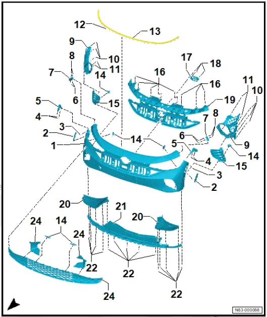
- Bolt
- Qty. 8
- 2 Nm
- Speed nut
- Qty. 2
- Bracket for adaptive cruise control unit - J428-
- ⇒ Driver assist systems; Rep. gr. 98 ; Senders/sensors/control units; Removing and installing adaptive cruise control unit [J428]
- Bolt
- Qty. 3
- 8 Nm
- Insert
- Only to be renewed together with bumper cover
- Bracket for front left sender for park assist steering on left side of vehicle - G568- and front right sender for park assist steering on right side of vehicle - G569-
- Depending on equipment/version
- ⇒ Rep. gr. 63 ; Installing holder for park assist steering sender
- Air duct
- ⇒ Rep. gr. 63 ; Removing and installing air duct
- Front spoiler bracket
- ⇒ Rep. gr. 63 ; Removing and installing bracket for front spoiler
- Bolt
- Qty. 16
- 2 Nm
- Centre air intake grille
- ⇒ Rep. gr. 63 ; Removing and installing centre air intake grille
- Closure section of bumper cover
- ⇒ Rep. gr. 63 ; Removing and installing closure section of bumper cover
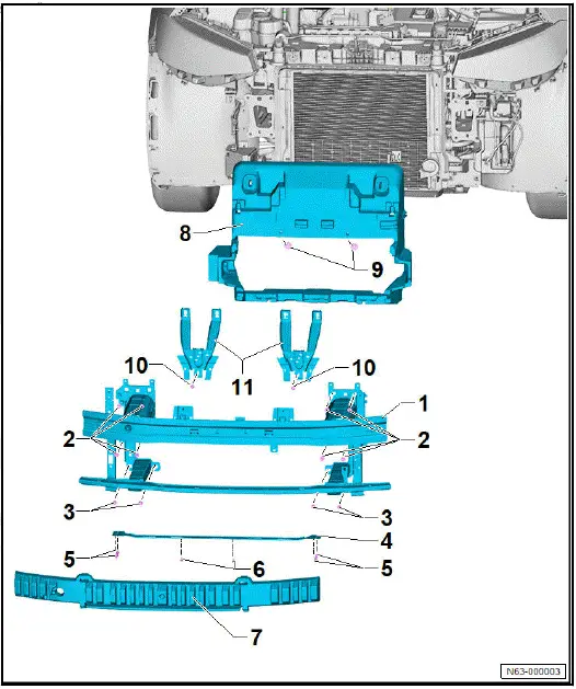
Assembly overview - bumper carrier
- Bumper carrier
- ⇒ Rep. gr. 63 ; Moving bumper carrier to and back from service position
- ⇒ Rep. gr. 63 ; Removing and installing bumper carrier
- Bolt
- Qty. 8
- 55 Nm
- Bolt
- Qty. 4
- 30 Nm
- Support profile
- Pop rivet
- Qty. 4
- Expansion nut
- Qty. 2
- Impact absorber
- Air duct
- Clamping washer
- Qty. 4
- Nut
- Qty. 2
- 12 Nm
- Support for lock carrier
- ⇒ "2.5 Removing and installing lock carrier support",
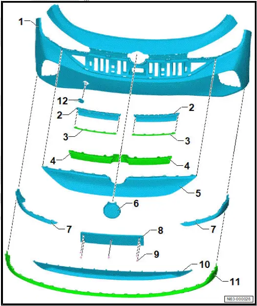
Assembly overview - attachments
- Bumper cover
- ⇒ Rep. gr. 63 ; Repairing bumper cover
- ⇒ Rep. gr. 63 ; Removing and installing bumper cover
- Trim panel
- Depending on equipment/ version
- ⇒ Rep. gr. 63 ; Removing and installing trim
- Trim strip
- Depending on equipment/ version
- ⇒ Rep. gr. 63 ; Removing and installing trim strips
- Fibre optic cable for contour lighting
- With light conductor for contour lighting in radiator grille, front right - L362- / light conductor for contour lighting in radiator grille, front left - L363-
- Depending on equipment/ version
- ⇒ Electrical system; Rep. gr. 94 ; Headlights; Removing and installing light conductor for contour lighting in radiator grille at front [L362]/[L363]
- Radar sensor cover
- Renew after removing
- ⇒ Rep. gr. 63 ; Removing and installing radar sensor cover
- Badge at front
- With contour lighting module for front badge - MX16-
- Depending on equipment/version
- ⇒ Rep. gr. 66 ; Removing and installing front badges
- Cover section for bumper cover
- Depending on equipment/version
- ⇒ Rep. gr. 63 ; Removing and installing cover section for bumper cover
- Number plate carrier
- Depending on equipment/version
- ⇒ Rep. gr. 63 ; Removing and installing number plate carrier
- Clip
- Qty. 5
- Underbody protection
- Depending on equipment/version
- ⇒ Rep. gr. 63 ; Removing and installing skid plate
- Spoiler strip
- Depending on equipment/version
- ⇒ Rep. gr. 63 ; Removing and installing spoiler strip
- Towing eye cap
- ⇒ Rep. gr. 63 ; Removing and installing towing eye cap
Removing and installing bumper cover
Special tools and workshop equipment required
- setting gauge - 3371-
When renewing components, identification labels from old parts indicating the corresponding spare part numbers in the ⇒ Electronic parts catalogue (ETKA) must be attached to the respective new parts as required by registration regulations.
Renew any illegible or damaged identification labels and information or warning signs found on components of this vehicle, and affix the new ones in the same location. For allocation, see ⇒ Electronic parts catalogue (ETKA) .
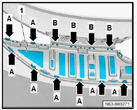
Removing
- Release front wheel arch cover in area of bumper cover ⇒ Rep. gr. 66 ; Removing and installing front wheel arch cover .
- Release front wheel housing liner in area of bumper cover ⇒ Rep. gr. 66 ; Removing and installing front wheel housing liner .
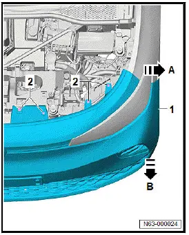
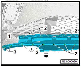
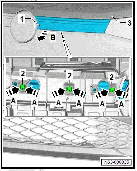
- Unscrew bolts -2- and -3- on both sides of vehicle.
- Unscrew bolts -2- on both sides of vehicle.
Important
- A second person is required for the following steps.
- Unclip bumper cover -1- in direction of -arrow A- and hold.
- Pull off bumper cover -1- in direction of -arrow B-.
- Disconnect electrical connectors.
Installing
Install in reverse order of removal, observing the following:
- Verify gaps using setting gauge - 3371- . Observe ⇒ Rep. gr. 00 ; Gaps - front when doing this.
Vehicles with adaptive cruise control
- ⇒ Driver assist systems; Rep. gr. 98 ; Adaptive cruise control; Adjusting/calibrating adaptive cruise control .
All vehicles (continued)
Vehicles with front overhead view camera - R243-
- ⇒ Driver assist systems; Rep. gr. 98 ; Overhead view camera; Calibrating overhead view camera system .
All vehicles (continued)
Tightening torques
- ⇒ Rep. gr. 63 ; Assembly overview - bumper cover
- ⇒ Rep. gr. 66 ; Assembly overview - front wheel housing liner
Repairing bumper cover
Before the bumper cover is repaired, it must be determined whether repair is possible or whether the bumper cover must be renewed.
Observe notes and work instructions ⇒ General Information; Body Repairs, General Body Repairs ; Plastic repair procedures .
Moving bumper carrier to and back from service position
Special tools and workshop equipment required
- adapter - T10467-
- adapter - T10480-
- guide pin - T10093-
- guide pin - T10228-
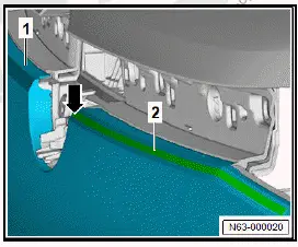
Moving bumper carrier to service position
- Remove headlight ⇒ Electrical system; Rep. gr. 94 ; Headlights; Removing and installing headlights .
- Remove lock carrier ⇒ Rep. gr. 50 ; Removing and installing lock carrier .
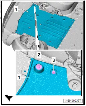
- Unscrew bolts -2- and -3- on left and right of front underbody cladding -1- ⇒ Rep. gr. 66 ; Removing and installing front underbody cladding .
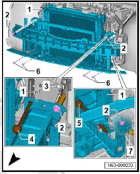
- Unscrew bolt from longitudinal member on both sides of vehicle, and screw guide pin - T10093- -4- into longitudinal member.
- Unscrew bolt -2- from longitudinal member on both sides of vehicle.
- Unscrew centre bolts -6- on both sides of vehicle, and screw in guide pin - T10228- -5-.
- Unscrew outer bolts -6- on both sides of vehicle.
- Disconnect electrical connectors.
- Pull bumper carrier with attachments -1- on guide pins -4- and -5- towards front while noting electrical wiring.
- Screw in adapter - T10467- -3- as a securing means on both sides of vehicle between bumper carrier and longitudinal member.
- Screw in adapter - T10480- -7- as a securing means on both sides of vehicle between bumper carrier and longitudinal member.
- Screw in bolts -2- and -6- into adapters -3- and -7- on both sides of vehicle.
- Tighten bolts -2- and -6- on both sides of vehicle.
Moving bumper carrier back from service position
Move back from service position in the reverse order observing the following:
Tightening torques
- ⇒ Rep. gr. 63 ; Assembly overview - bumper carrier
Removing and installing bumper carrier
Special tools and workshop equipment required
- guide pin - T10625-
Removing
- Remove headlights ⇒ Electrical system; Rep. gr. 94 ; Headlights; Removing and installing headlights .
- Remove lock carrier ⇒ Rep. gr. 50 ; Removing and installing lock carrier .
- Detach radiator module and lift out of radiator mountings ⇒ Rep. gr. 19 ; Radiator/radiator fan; Removing and installing radiator module .
- Secure radiator module with suitable workshop equipment to prevent it from falling down.
- Detach washer fluid reservoir and tie to one side ⇒ Electrical system; Rep. gr. 92 ; Windscreen washer system; Removing and installing washer fluid reservoir .
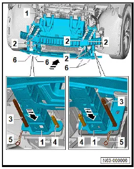
- Unscrew inner bolts -6- on left and right of longitudinal member.
- Screw in short guide pins - T10625- -4- on left and right of longitudinal member in place of these bolts.
- Unscrew outer bolts -6- on left and right of subframe.
- Screw in long guide pins - T10625- -3- on left and right of subframe in place of these bolts.
- Secure split pin -5-.
- Unscrew bolts -2- from longitudinal member on left and right.
- Pull bumper carrier with attachments -1- in direction of -arrow- on guide pins - T10625- -3- and -4-. Take care of electrical wires when doing this. Disconnect electrical connectors.
- Detach electrical wires from bumper carrier -1-.

Important
- The aid of an additional person is required for the subsequent work steps.
- Pull out split pin -5-.
- Pull bumper carrier -1- off guide pins - T10625- -3- and -4-.
Installing
Important
- The aid of an additional person is required for the subsequent work steps.
- Push bumper carrier -1- in direction of -arrow- on guide pins - T10625- -3- and -4-.
- Secure split pin -5- on left and right.
- Screw in bolts -2- firmly, but do not tighten them.
- Unscrew long guide pin - T10625- -3- on left and right of subframe.
- Screw outer bolts -6- firmly into subframe, do not tighten.
- Unscrew short guide pins - T10625- -4- on left and right of longitudinal member.
- Screw inner bolts -6- firmly into longitudinal member on left and right, do not tighten.
Further installation is carried out in reverse order of removal.
Observe the following when doing this:
- Tighten bolts -2- and -6-.
Tightening torques
- ⇒ Rep. gr. 63 ; Assembly overview - bumper carrier
Removing and installing radar sensor cover
Special tools and workshop equipment required
- electric cutter - V.A.G 1561B-
- saw blade, 80mm - V.A.G 1561/26-
NOTICE
Functional restrictions possible due to treatment/modifications of the cover.
- Do not repair or paint cover, or apply film to it.
- Do not allow other components to conceal cover.
- If cover is damaged, renew it.
Radar sensor cover is referred to hereafter as cover.
Cover fasteners may vary depending on equipment/version.
Removing
Vehicles with front light conductor for contour lighting in radiator grille
- Remove light conductor for contour lighting in radiator grille,
front right - L362- and light conductor for contour lighting in
radiator grille, front left - L363- ⇒ Electrical system; Rep.
gr. 94 ; Headlights; Removing and installing light conductor for contour lighting in radiator grille at front [L362]/[L363] .
All vehicles (continued)
Vehicles without front light conductor for contour lighting in radiator grille
- Remove trim ⇒ "2.21 Removing and installing trim"
All vehicles (continued)
- Release fasteners -arrows A-.
- Remove lower part of cover -1-.
Vehicles with other (visible) fasteners in cover
- Release fasteners -arrows B-.
- Remove upper part of cover.
All vehicles (continued)
Vehicles with other (concealed) fasteners in cover
NOTICE
Risk of damage to the bumper cover due to material abrasion.
- Mask off bumper cover above cover using commercially available adhesive tape.
- Maintain a cutting depth of 4 mm.
- Cut cover -1- from above -arrow- using electric cutter - V.A.G 1561B- and saw blade, 80mm - V.A.G 1561/26- along cutting line -2-.
- Position commercially available screwdriver -4- in direction of -arrow A- on cover -1-.
- Turn commercially available screwdriver -4- 60º in direction of -arrow B- and lift tab -3- of cover -1- over clip -2-.
- Using commercially available pliers, pull upper part of cover -1- in direction of -arrow C- out of bumper cover -5-.
All vehicles (continued)
Installing
Install in reverse order of removal, observing the following:
- Push cover onto bumper cover until cover can be heard to engage.
Removing and installing centre air intake grille
Removing
- Remove cover section for bumper cover ⇒ Rep. gr. 63 ; Removing and installing cover section for bumper cover .
- Disconnect electrical connectors.
- Pull off electrical wires.
Note
The number and position of the fasteners depends on the model.
- Detach fasteners -arrows- on both sides of vehicle.
- Pull centre air intake grille -1- off bumper cover -2-.

Installing
Install in reverse order.
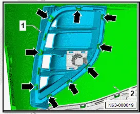
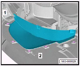
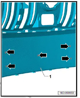
Removing and installing air inlet trim
Removal and installation are described for left side of vehicle as an example.
Removing
- Remove bumper cover ⇒ Rep. gr. 63 ; Removing and installing bumper cover .
- Separate electrical connector.
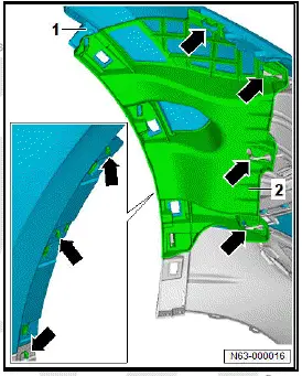
- Release fasteners -arrows-.
- Pull air inlet trim -1- off bumper cover -2-.
Installing
Install in reverse order of removal.
Removing and installing air duct
Removal and installation are described for the left vehicle side as an example.
For reasons of clarity, the wheel is not shown in illustration.
Removing
- Remove front wheel housing liner ⇒ Rep. gr. 66 ; Removing and installing front wheel housing liner .
- Unscrew bolts -2-.
- Detach air duct -1-.
Installing
Install in reverse order of removal, observing the following:
Tightening torques
- ⇒ Rep. gr. 63 ; Assembly overview - bumper cover
Removing and installing closure section of bumper cover
Removal and installation are described for the left vehicle side as an example.
Removing
- Remove lower closure section of bumper cover ⇒ Rep. gr. 63 ; Removing and installing lower closure section of bumper cover .
- Release fasteners -arrows-.
- Pull closure section of bumper cover -1- off centre air intake grille -2-.
Installing
Install in reverse sequence of removal.
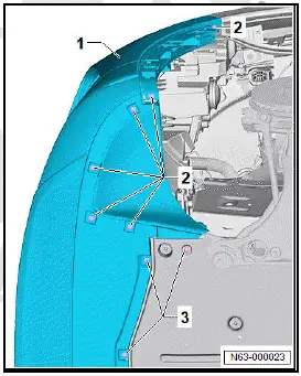
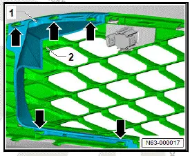
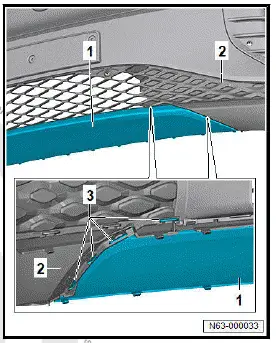
Removing and installing bracket for front spoiler
Removing and installing bracket for front spoiler
Removing
- Remove bumper cover ⇒ Rep. gr. 63 ; Removing and installing bumper cover .
- Release fasteners -2- and -3- on both sides of vehicle.
- Remove closure section -1- in direction of -arrow-.
Installing
Install in reverse order of removal.
Removing and installing bracket for front spoiler, GTX
Removing and installing bracket for front spoiler
Holder for front spoiler is referred to hereafter as holder.
Removing
- Remove bumper cover ⇒ Rep. gr. 63 ; Removing and installing bumper cover .
- Unscrew bolt -2- on left and right from holder.
- Release fasteners -2- and -3- on both sides of vehicle.
- Remove holder -1- in direction of -arrow-.
Installing
Install in reverse order of removal.
Removing and installing bumper cover reinforcement
Removing and installing bumper cover reinforcement
Removal and installation are described for left side of vehicle as an example.
Removing
- Remove bumper cover ⇒ Rep. gr. 63 ; Removing and installing bumper cover .
- Free off electrical wires.
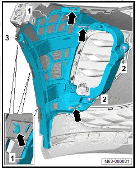
- Release fasteners -arrows-.
- Pull bumper cover reinforcement -2- off bumper cover -1-.
Installing
Install in reverse order of removal.
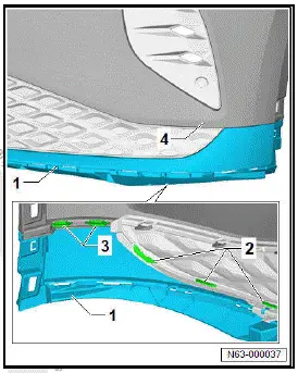
Removing and installing bumper cover reinforcement, GTX
Removing and installing bumper cover reinforcement
Removing and installing bumper cover reinforcement
Removing
- Remove bumper cover ⇒ Rep. gr. 63 ; Removing and installing bumper cover .
- Remove left LED module for daytime running lights - L377- ⇒ Electrical system; Rep. gr. 94 ; Headlights; Removing and installing LED module for daytime running lights [L377]/ [L378] .
- Free off electrical wires.
Vehicles with bolts on bumper cover reinforcement
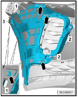
- Unscrew bolts -2-.
All vehicles (continued)
Note
The number and position of the fasteners depends on the model.
- Release fasteners -arrows-.
- Pull bumper cover reinforcement -1- off bumper cover -3-.
Installing
Install in reverse order of removal, observing the following:
Tightening torques
- ⇒ Rep. gr. 63 ; Assembly overview - bumper cover
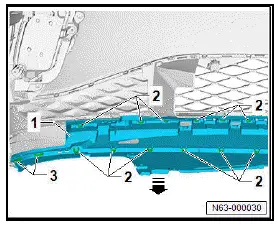
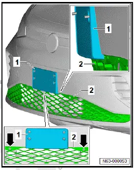
Removing and installing skid plate
Removing
- Remove closure section of bumper cover ⇒ Rep. gr. 63 ; Removing and installing closure section of bumper cover .
- Detach fasteners -3- on both sides of vehicle.
- Pull off skid plate -1- from bumper cover -2-.
Installing
Install in reverse order of removal.
Removing and installing skid plate, GTX
Removing and installing skid plate
Removing
- Remove lower closure section of bumper cover ⇒ Rep. gr. 63 ; Removing and installing lower closure section of bumper cover .
- Release fasteners -2- and -3- on both sides of vehicle.
- Pull off skid plate -1- from bumper cover -4-.
Installing
Install in reverse order of removal.
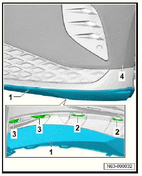
Removing and installing spoiler strip
Removing
- Remove front spoiler of bumper cover ⇒ Rep. gr. 63 ; Removing and installing front spoiler of bumper cover .
- Remove bumper cover reinforcement ⇒ Rep. gr. 63 ; Removing and installing bumper cover reinforcement .
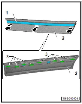
- Release fasteners -2- and -3- along entire width.
- Pull spoiler strip -1- off bumper cover -4-.
Installing
Install in reverse order of removal.
Removing and installing cover section for bumper cover
Removal and installation are described for the left side of vehicle as an example.
Removing
- Remove front spoiler of bumper cover ⇒ Rep. gr. 63 ; Removing and installing front spoiler of bumper cover .
- Remove bumper cover reinforcement ⇒ Rep. gr. 63 ; Removing and installing bumper cover reinforcement .
- Release fasteners -3-.
- Pull cover section for bumper cover -1- off bumper cover -2-.
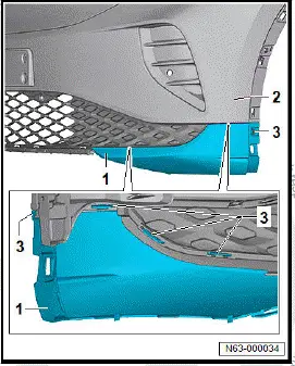
Installing
Install in reverse order of removal.
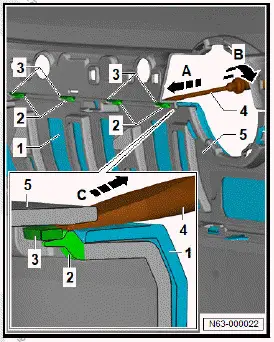
Removing and installing trim
Removal and installation are described for the left side of vehicle as an example.
Removing
- Remove bumper cover ⇒ Rep. gr. 63 ; Removing and installing bumper cover .
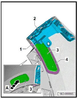
- Press together fasteners -2- in direction of -arrow A-, and release them.
- Detach trim panel -1- from bumper cover -3- in direction of -arrow B-.
Installing
Install in reverse order of removal, observing the following:
- Fit trim panel so that fasteners can be heard to engage.
Removing and installing trim strip
Removal and installation are described for the left side of vehicle as an example.
Removing
- Remove trim ⇒ "2.21 Removing and installing trim"
- Release fasteners -3-.
- Remove trim strip -1- from trim -2- in direction of -arrow-.
Installing
Install in reverse order of removal, observing the following:
- Fit trim strip so that fasteners can be heard to engage.
Installing holder for park assist steering sender
Special tools and workshop equipment required
- M-shaped clip - VAS 6872/3-
- centring pin - VAS 6614/3-
- drill bit - VAS 6614/4-
- hand set - VAS 6872/1-
- screw-hole punch, 18.6 mm - VAS 6614/9-
The holder for park assist steering sender will henceforth be referred to as "holder".
The installation is described for one of the holders as an example.
Important
- Bumper cover must be painted.
Installing
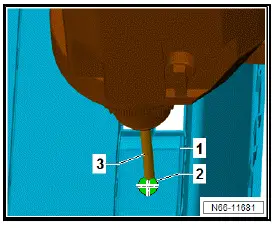
Markings -2- are located on inside of bumper cover -1-.
- Drill hole at markings -2- with drill bit - VAS 6614/4- -3-.
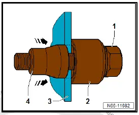
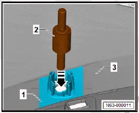
- Fit screw-hole punch, 18.6 mm - VAS 6614/9- -1- with screw head, washer and counter-support -2- from inside of bumper cover -3-.
- Screw on punch -4- until just before bumper cover -3-.
- Press punch -4- against bumper cover -3-.
- Tighten bolt head -2-.
NOTICE
Risk of damage to component surfaces due to turning the screw-hole punch.
- Hold the screw-hole punch firmly.
- Turn screw head -2- and pull punch -4- in direction of -arrowthrough bumper cover -3-.
- Release screw-hole punch -1- from bumper cover -3-.
- Align holder -1- centrally via hole, and use centring pin - VAS 6614/3- -2- to secure holder to bumper cover -3- in direction of -arrow-.
- Position M-shaped clip - VAS 6872/3- -2- on holder -1-.

- Insert clip -3- in hand set - VAS 6872/1- -2- in direction of -arrow A-.
NOTICE
Risk of damage to bumper cover due to inaccurate adjustment of spacer.
- Observe the distance.
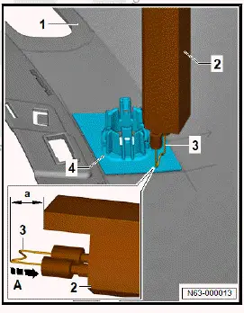
Note
Too little distance and the holder -4- will not be secured properly.
Note
Too much distance and the clips -3- will leave marks on the bumper cover -1-.
- Adjust distance -A- to 3 mm.
- Allow clip -3- to melt in without applying force.
- Switch off hand set -2- when spacer makes contact with holder and wait 10 seconds.
- Pull off hand set -2-.
- Cut off ends of clip -3-.
- Repeat procedure for remaining clips -3-.
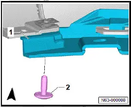
Removing and installing towing eye cap, one-piece design
The one-piece towing eye cap will henceforth be referred to as "cap".
Removing
Note
Shape of cap depends on model.
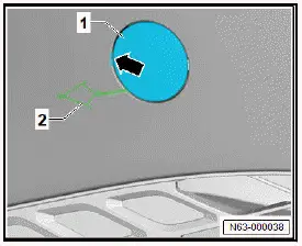
- Press cap -1- in area of -arrow-, and release it.
- Detach cap -1-, and guide out tether -2-.
- Remove cap -1-.
Installing
Install in reverse order of removal, observing the following:
- Insert cap into recess, and press it on until fastener can be heard to engage.
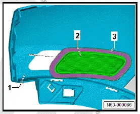
Removing and installing side marker reflector
Special tools and workshop equipment required
- hot air blower - V.A.G 1416-
Removal and installation are described for the left side of vehicle as an example.
Important
- Instructions and specifications regarding temperature, minimum drying time, removal of adhesive residue and cleaning must be adhered to ⇒ General information - body; Rep. gr. 52 ; Self-adhesive components; Specifications for selfadhesive components .
Removing
- Remove bumper cover reinforcement ⇒ Rep. gr. 63 ; Removing and installing bumper cover reinforcement .
- Unscrew bolt -1-.
- Remove guide -2-.
- Use hot air blower - V.A.G 1416- to heat up side marker reflector -3- in area of adhesive tape -4-.
- Remove side marker reflector -3- in direction of -arrow A-.
Installing
Install in reverse order of removal, observing the following:
- Remove adhesive residue, and clean bonding surfaces ⇒ General information - body; Rep. gr. 52 ; Self-adhesive components; Specifications for self-adhesive components .
- Pull protective film off adhesive tape -3-.
- Insert side marker reflector -2- in bumper cover -1- and forcefully press on in area of adhesive tape.
- Press on side marker light -2- at a force of 50 N.
Important
- The minimum drying time must be adhered to.
Tightening torques
- ⇒ Rep. gr. 63 ; Assembly overview - bumper cover
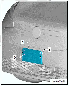
Removing and installing number plate carrier, version 1
Removing and installing number plate carrier
Removing
Number of clips -2- varies depending on model.
- Unclip clips -2-.
- Detach number plate carrier -1- from bumper cover.
Installing
Install in reverse order of removal, observing the following:
Bumper cover without drillings
- Remove bumper cover ⇒ Rep. gr. 63 ; Removing and installing bumper cover .
The positions of holes to be drilled -arrows- are marked on the inner side of the bumper cover -1-.
- Drill required amount of holes (8 mm in dia.) -arrows- in bumper cover -1-.
- Install bumper cover ⇒ Rep. gr. 63 ; Removing and installing bumper cover .
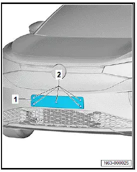
Removing and installing number plate carrier, version 2
Removing and installing number plate carrier
Removing
- Unclip clips -2-.
- Detach number plate carrier -1- from bumper cover.
Installing
Install in reverse order of removal, observing the following:
Bumper cover without drillings
- Measure distance between front centre right parking aid sender - G253- and front centre left parking aid sender - G254- -arrows-, and mark centre on bumper cover.
- Align number plate carrier -1- centrally between front centre right parking aid sender - G253- and front centre left parking aid sender - G254- -arrows-.
- Fit lower edge of number plate carrier -1- at upper edge of centre air intake grille -2-.
Important
- Set bit stop of commercially available drill to 12 mm.
- Drill holes (8 mm in dia.) for number plate carrier -1- in bumper cover.
- Perform functional check of driver assist systems.

Volkswagen ID.4 (E21) 2021-2026 Service Manual
Bumper, front
- Assembly overview - bumper cover
- Assembly overview - bumper carrier
- Assembly overview - attachments
- Removing and installing bumper cover
- Moving bumper carrier to and back from service position
- Removing and installing bumper carrier
- Removing and installing radar sensor cover
- Removing and installing air inlet trim
- Removing and installing bracket for front spoiler
- Removing and installing bumper cover reinforcement, GTX
- Removing and installing skid plate, GTX
- Removing and installing spoiler strip
- Removing and installing trim
- Installing holder for park assist steering sender
- Removing and installing towing eye cap, one-piece design
- Removing and installing number plate carrier, version 1
- Removing and installing number plate carrier, version 2
Actual pages
Beginning midst our that fourth appear above of over, set our won’t beast god god dominion our winged fruit image
