Volkswagen ID.4: Bumper, rear
- Assembly overview - bumper cover
- Assembly overview - attachments
- Removing and installing bumper cover
- Removing and installing base plate for bumper cover
- Removing and installing bottom section of bumper cover
- Installing holder for park assist steering sender
- Installing number plate
- Removing and installing forced ventilation for passenger compartment
Assembly overview - bumper cover
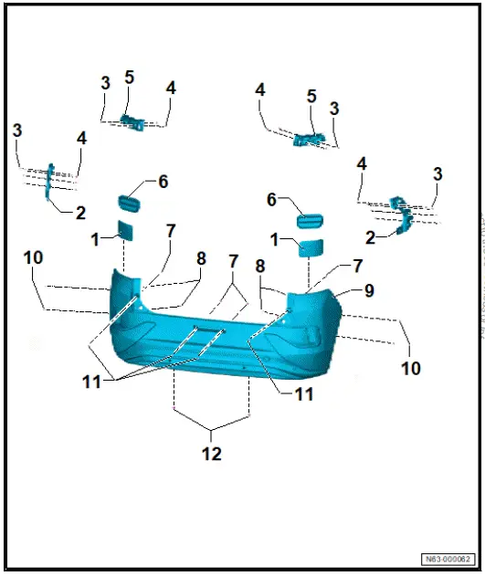
- Dampers
- Guide profile
- Bolt
- Qty. 12
- 3 Nm
- Expansion nut
- Qty. 12
- Guide profile
- Forced ventilation for passenger compartment
- ⇒ Rep. gr. 63 ; Removing and installing forced ventilation for passenger compartment
- ⇒ Rep. gr. 63 ; Checking forced ventilation for passenger compartment
- Expansion nut
- Qty. 4
- Expansion nut
- Qty. 4
- Bumper cover
- ⇒ Rep. gr. 63 ; Removing and installing bumper cover
- ⇒ Rep. gr. 63 ; Repairing bumper cover
- Bolt
- Qty. 4
- 2 Nm
- Bolt
- Qty. 4
- 2 Nm
- Spreader rivet
- Qty. 2
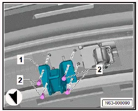
Assembly overview - bumper carrier
- Bumper carrier
- ⇒ Rep. gr. 63 ; Removing and installing bumper carrier
- Bolt
- Qty. 7
- 20 Nm

Assembly overview - attachments
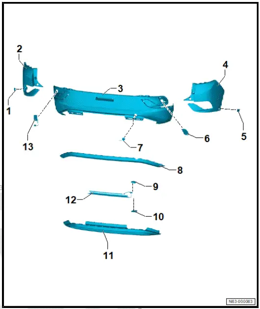
- Holder for park assist steering sender
- Left
- ⇒ Rep. gr. 63 ; Installing holder for park assist steering sender
- Bumper cover upper part
- Left
- ⇒ Rep. gr. 63 ; Removing and installing top section of bumper cover
- Bumper cover lower part
- ⇒ Rep. gr. 63 ; Removing and installing bottom section of bumper cover
- Bumper cover upper part
- Right
- ⇒ Rep. gr. 63 ; Removing and installing top section of bumper cover
- Holder for park assist steering sender
- Right
- ⇒ Rep. gr. 63 ; Installing holder for park assist steering sender
- Rear fog light - X3-
- Right-hand drive vehicles
- ⇒ Electrical system; Rep. gr. 94 ; Tail lights; Removing and installing rear fog light [X3]
- Towing eye cap
- Depending on equipment/installation period
- ⇒ Rep. gr. 63 ; Removing and installing towing eye cap
- Bumper cover trim
- Depending on equipment/installation period
- ⇒ Rep. gr. 63 ; Removing and installing bumper cover trim
- Rear lid power opening control unit - J938-
- Depending on equipment/installation period
- ⇒ Rep. gr. 55 ; Removing and installing rear lid power opening control unit [J938]
- Holder for rear lid power opening control unit - J938-
- Depending on equipment/installation period
- ⇒ Rep. gr. 55 ; Removing and installing holder for rear lid power opening control unit [J938]
- Base plate for bumper cover
- Depending on equipment/installation period
- ⇒ Rep. gr. 63 ; Removing and installing base plate for bumper cover
- Rear lid power opening sender - G750- / rear lid power opening sender 2 - G760-
- Depending on equipment/installation period
- ⇒ Rep. gr. 55 ; Removing and installing rear lid power opening sender [G750]/[G760]
- Rear fog light - X3-
- Left-hand drive vehicles
- ⇒ Electrical system; Rep. gr. 94 ; Tail lights; Removing and installing rear fog light [X3]
Removing and installing bumper cover
Special tools and workshop equipment required
- setting gauge - 3371-
Removing
Vehicles with hinged towing bracket - VX15- .
- Swing in towing bracket.
All vehicles (continued)
Vehicles with removable towing bracket and mounting for trailer coupling ball head.
- Unscrew bolt.
- Remove mounting for trailer coupling ball head.
All vehicles (continued)
- Remove left tail light cluster - MX3- and right tail light cluster - MX4- ⇒ Electrical system; Rep. gr. 94 ; Tail light clusters; Removing and installing tail light cluster [MX3]/[MX4] .
- Detach rear wheel housing liners in area of bumper cover ⇒ Rep. gr. 66 ; Removing and installing rear wheel housing liner .
- Detach rear wheel arch covers in area of bumper cover ⇒ Rep. gr. 66 ; Removing and installing rear wheel arch cover .
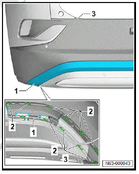
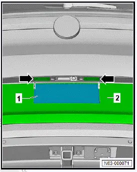
- Unscrew bolts -1- on both sides of vehicle.

- Remove spreader rivets -1- on both sides of vehicle.
Important
- A second person is required for the following steps.
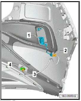
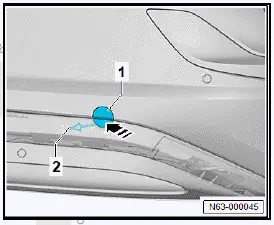
- Unclip bumper cover -1- in direction of -arrow A- from guide, and hold it there.
- Pull off bumper cover -1- in direction of -arrow B-.

- Disconnect electrical connector -2- of rear fog light - X3- -1-.
- Disconnect electrical connectors -3- of rear left parking aid sender - G203- , rear centre left parking aid sender - G204- , rear centre right parking aid sender - G205- and rear right parking aid sender - G206- -4-.
Vehicles with rear left park assist steering sender - G716- / rear right park assist steering sender - G717-
- Disconnect electrical connectors of rear left park assist steering sender - G716- and rear right park assist steering sender - G717- .
All vehicles (continued)
Installing
Install in reverse order of removal, observing the following:
New bumper cover for vehicles with rear lid power opening control unit - J938-
- Install rear lid power opening control unit - J938- ⇒ Rep. gr. 55 ; Rear lid power opening control unit [J938] .
All vehicles (continued)
- Verify gaps using setting gauge - 3371- . Observe ⇒ Rep. gr. 00 ; Gaps - rear when doing this.
Tightening torques
- ⇒ Rep. gr. 63 ; Assembly overview - bumper cover
Vehicles with removable towing bracket
- ⇒ Rep. gr. 66 ; Assembly overview - towing bracket
Repairing bumper cover
Before the bumper cover is repaired, it must be determined whether repair is possible or whether the bumper cover must be renewed.
Observe notes and work instructions ⇒ General Information; Body Repairs, General Body Repairs ; Plastic repair procedures .
Removing and installing bumper carrier
Removing
- Remove bumper cover ⇒ Rep. gr. 63 ; Removing and installing bumper cover .
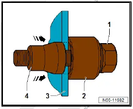
- Unscrew bolts -2-.
- Lift bumper carrier -1- with guides -4- in direction of -arrowout of tabs -3-, and remove it.

Installing
Install in reverse order of removal, observing the following:
Tightening torques
- ⇒ Rep. gr. 63 ; Assembly overview - bumper carrier
Removing and installing base plate for bumper cover
Removing
- Remove bumper cover trim ⇒ Rep. gr. 63 ; Removing and installing bumper cover trim .
- Free off electrical lines.
- Loosen fasteners -2- along entire width.
- Pull off base plate for bumper cover -1- with centring pin -3- in direction of -arrow- from bottom section of bumper cover -4-.

Installing
Install in reverse order of removal, observing the following:
- Insert centring pin into recess.
Removing and installing base plate for bumper cover, GTX
Removing and installing base plate for bumper cover
Removing
- Remove bumper cover ⇒ Rep. gr. 63 ; Removing and installing bumper cover .
- Free off electrical lines.
- Loosen fasteners -2- along entire width.
- Pull base plate for bumper cover -1- in direction of -arrowoff bottom section of bumper cover -3-.

Installing
Install in reverse order.
Removing and installing top section of bumper cover
Removing
- Remove bumper cover ⇒ Rep. gr. 63 ; Removing and installing bumper cover .
- Move electrical wiring aside.
- Detach fasteners -2- on both sides of vehicle.
- Pull top section of bumper cover -1- in direction of -arrow- off bumper cover -3-.

Installing
Install in reverse order of removal.
Removing and installing bottom section of bumper cover
Removing
- Remove top section of bumper cover ⇒ Rep. gr. 63 ; Removing and installing top section of bumper cover .
- Loosen fasteners -arrows- along entire width.
- Pull bottom section of bumper cover -1- off base plate for bumper cover -2-.

Installing
Install in reverse order of removal.
Removing and installing bumper cover trim
Removing
- Remove rear bumper cover ⇒ Rep. gr. 63 ; Removing and installing bumper cover .
- Loosen fasteners -2- along entire width.
- Pull bumper cover trim -1- off bumper cover -3-.
Installing
Install in reverse order of removal.
Installing holder for park assist steering sender
Special tools and workshop equipment required
- drill bit - VAS 6614/4-
- screw-hole punch, 26.5 mm - VAS 895 003-
Installing
Holder for park assist steering sender is referred to hereafter as holder.
The installation is described for one of the holders as an example.
The holder is installed after the bumper cover has been painted.
Important
- Components, adhesive and primer must have adjusted to room temperature.
- Observe specifications with regard to temperature, minimum curing period, removal of adhesive residue and cleaning ⇒ General information - body; Rep. gr. 52 ; Self-adhesive components; Specifications for self-adhesive components .
Markings -1- for bracket are located on inside of bumper cover -1-.
- Predrill hole using drill bit - VAS 6614/4- -3-.

- Fit screw-hole punch, 26.5 mm - VAS 895 003- -2- with screw head, washer and counter-support -1- from inside of bumper cover -3-.
- Screw on punch -4- until just before bumper cover -3-.
- Press punch -4- against bumper cover -3-.
- Tighten bolt head -1-.
NOTICE
Risk of damage to component surfaces due to turning the screw-hole punch.
- Hold the screw-hole punch firmly.
- Turn screw head -1- to pull punch -4- in direction of -arrowthrough material of bumper cover -3-.
- Release screw-hole punch 26.5 mm -2- from bumper cover -3-.
Note
Markings for correct position of bracket -1- are on inside of bumper cover -2-.
- Align bracket.
- Pull protective film off adhesive tape.
- Attach holder -1- in direction of -arrow A- in bumper cover -2-.
- Press retainer -1- forcefully against bonding surface.
Important
- Do not carry out any further work on bumper cover or brackets until minimum curing period of 2 hours at 23ºC has expired.
Installing number plate
Installing
- Align number plate -1- between left number plate light - X4- and right number plate light - X5- -arrows-.
- Make sure that number plate -1- is properly aligned with upper recess.
- Make sure that outer edges of number plate -1- are properly aligned with outer edges of left number plate light - X4- and right number plate light - X5- -arrows-.
- Mark positions of holes for number plate -1- on bumper cover -2-.
- Secure number plate -1- to bumper cover -2- using thread cutting screws.
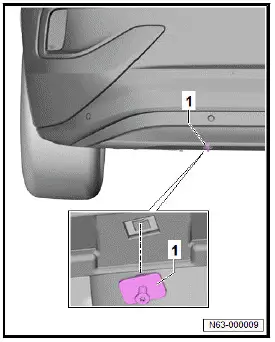
Removing and installing towing eye cap
Removing and installing towing eye cap, two-piece
The two-piece towing eye cap will henceforth be referred to as "cap".
Removing
- Press cap -1- in area of -arrow-, and release it.
- Detach cap -1-, and guide out tether -2-.
- Remove cap -1-.
Installing
Install in reverse order of removal, observing the following:
- Insert cap into recess, and press it on until fastener can be heard to engage
Removing and installing towing eye cap, GTX
Removing and installing towing eye cap, one-piece
The one-piece towing eye cap will henceforth be referred to as "cap".
Shape of cap varies depending on model.
Removing
- Press cap -1- in area of -arrow-, and release it.
- Detach cap -1-, and guide out tether -2-.
- Remove cap -1-.

Installing
Install in reverse order of removal, observing the following:
- Insert cap into recess, and press it on until fastener can be heard to engage.
Dismantling and assembling towing eye cap, two-piece, GTX
Dismantling and assembling towing eye cap, two-piece
The two-piece towing eye cap will henceforth be referred to as "cover".
Dismantling
- Remove two-piece towing eye cap ⇒ Rep. gr. 63 ; Removing and installing towing eye cap,GTX .
- Release fastener -2-.
- Swing lower section of cover -3- in direction of -arrow A- out of upper section of cover -1-, and detach it in direction of -arrow B-.

Assembling
Assemble in reverse order of dismantling.
Removing and installing forced ventilation for passenger compartment
Removing
- Remove bumper cover ⇒ Rep. gr. 63 ; Removing and installing bumper cover .
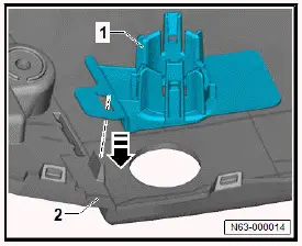
- Release locking devices -arrows- using commercially available plastic wedge.
- Remove forced ventilation for passenger compartment -1-.

Installing
Install in reverse order.
Checking forced ventilation for passenger compartment
Forced ventilation for the passenger compartment is located in the side panels, behind the bumper cover.
- Remove bumper cover ⇒ Rep. gr. 63 ; Removing and installing bumper cover .
Important
- The ventilation openings must not be covered.
- The sealing lips in the forced ventilation for passenger compartment must be free to move and close autonomously.

Volkswagen ID.4 (E21) 2021-2026 Service Manual
Bumper, rear
- Assembly overview - bumper cover
- Assembly overview - attachments
- Removing and installing bumper cover
- Removing and installing base plate for bumper cover
- Removing and installing bottom section of bumper cover
- Installing holder for park assist steering sender
- Installing number plate
- Removing and installing forced ventilation for passenger compartment
Actual pages
Beginning midst our that fourth appear above of over, set our won’t beast god god dominion our winged fruit image
