Volkswagen ID.4: Door
- Assembly overview - door
- Removing and installing inner door seal
- Removing and installing outer door seal
- Removing and installing door
- Adjusting door
- Adjusting striker pin
- Removing and installing door hinge
- Removing and installing door arrester
Assembly overview - door
Overview is shown for left side of vehicle as an example
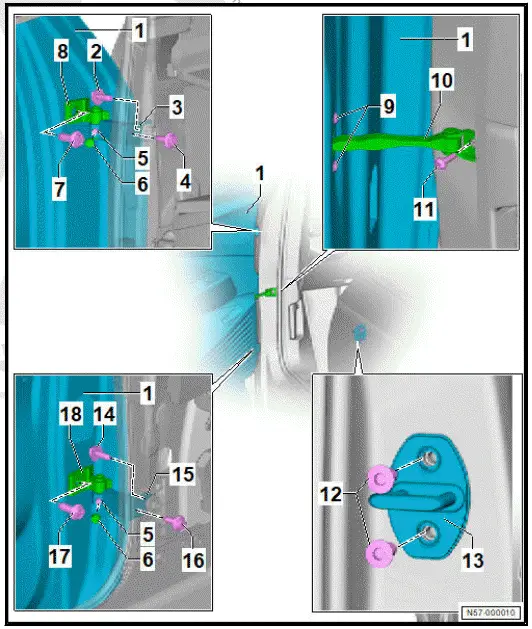
- Door
- ⇒ Rep. gr. 57 ; Removing and installing door
- ⇒ Rep. gr. 57 ; Adjusting door
- Bolt
- Renew after removing
- 20 Nm +90º
- Lower section of door hinge
- ⇒ Rep. gr. 57 ; Removing and installing door hinge
- Bolt
- Renew after removing
- 20 Nm +90º
- Threaded pin
- 27 Nm
- Cap
- Bolt
- 50 Nm
- Upper section of door hinge
- ⇒ Rep. gr. 57 ; Removing and installing door hinge
- Bolt
- Qty. 2
- 8 Nm
- Door arrester
- ⇒ Rep. gr. 57 ; Removing and installing door arrester
- Bolt
- 30 Nm
- Bolt
- Qty. 2
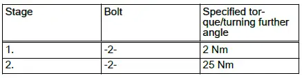
- Specified torque and tightening sequence
- Striker pin
- ⇒ Rep. gr. 57 ; Removing and installing striker pin
- ⇒ Rep. gr. 57 ; Adjusting striker pin
- Bolt
- Renew after removing
- 20 Nm +90º
- Lower section of door hinge
- ⇒ Rep. gr. 57 ; Removing and installing door hinge
- Bolt
- Renew after removing
- 20 Nm +90º
- Bolt
- 50 Nm
- Upper section of door hinge
- ⇒ Rep. gr. 57 ; Removing and installing door hinge
Specified torque and tightening sequence
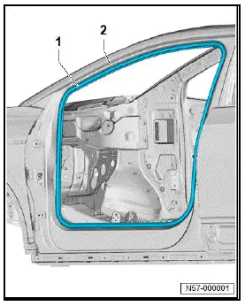
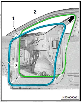
Assembly overview - door seals
- Door joint seal
- Renew after removing
- ⇒ Rep. gr. 57 ; Removing and installing outer door seal
- Inner door seal
- Renew after removing
- ⇒ Rep. gr. 57 ; Removing and installing inner door seal
- Door
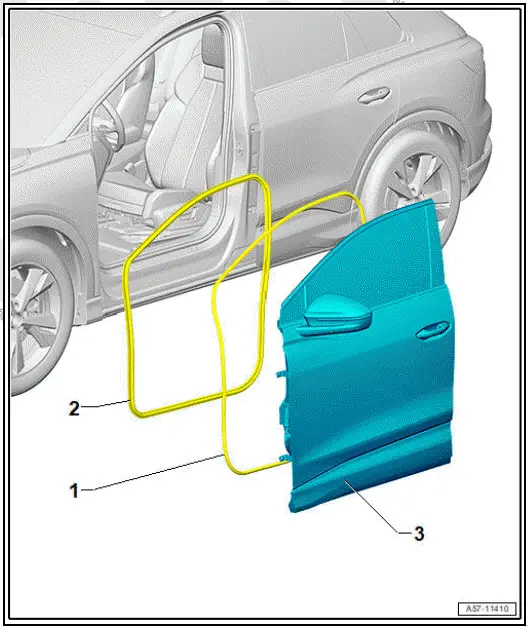
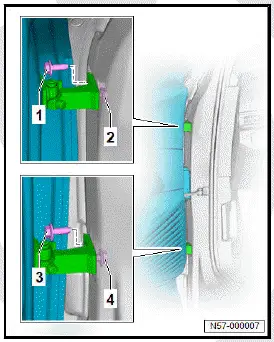
Removing and installing inner door seal
For reasons of clarity, the front door is not shown in the illustrations of the following work procedures.
Removal and installation are described for left side of vehicle as an example.
Removing
- Remove front sill panel moulding ⇒ General body repairs, interior; Rep. gr. 70 ; Trims, interior; Removing and installing front sill panel moulding .
- Remove upper A-pillar trim ⇒ General body repairs, interior; Rep. gr. 70 ; Trims, interior; Removing and installing A-pillar trim .
- Remove lower A-pillar trim ⇒ General body repairs, interior; Rep. gr. 70 ; Trims, interior; Removing and installing lower A-pillar trim .
- Remove upper B-pillar trim ⇒ General body repairs, interior; Rep. gr. 70 ; Trims, interior; Removing and installing B-pillar trim .
- Remove lower B-pillar trim ⇒ General body repairs, interior; Rep. gr. 70 ; Trims, interior; Removing and installing lower B-pillar trim .
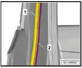
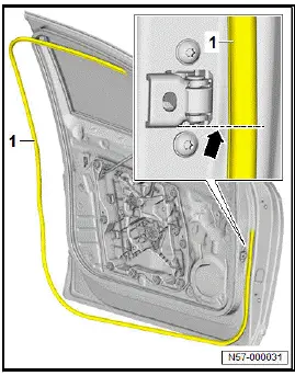
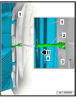
- Pull off inner door seal -1- from body flange -2-.
Installing
NOTICE
When the inner door seal is pulled off, the flanks of the seal may get bent up so that the inner door seal no longer provides the required sealing function at some points.
Water ingress or wind noise may result.
- If the inner door seal has only been pulled off partially, compress the seal flanks, then install the inner door seal.
- Make sure that adjacent trims are located in the beading of the inner door seal.
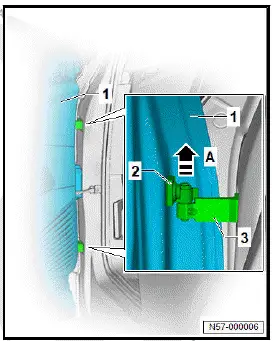
- Start installing inner door seal -1- at top radius -arrow- of body flange -2-.
Important
- Do not kink vulcanised point -3-.
- Align vulcanised point -3- with threaded connection of door arrester.
- Apply inner door seal -1- in lower area using plastic hammer.
- Apply inner door seal -1- in upper area by hand.
Continue installation in reverse order of removal.
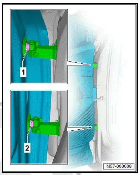
Removing and installing outer door seal
Special tools and workshop equipment required
- gasket shears - VAS 211 011-
- punch tool - VAS 895 025-
- roller - T40400-
Removal and installation are described for the left side of vehicle as an example.
Important
- Instructions and specifications regarding temperature, minimum drying time, removal of adhesive residue and cleaning must be adhered to ⇒ General information - body; Rep.gr. 52 ; Self-adhesive components; Specifications for selfadhesive components .
Removing
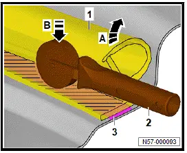
- Mark position of outer door seal -1- all around with adhesive tape -2-.
NOTICE
Risk of damage to surfaces of components.
- Mask off A-pillar in area of door arrester using commercially available adhesive tape.
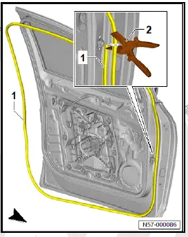
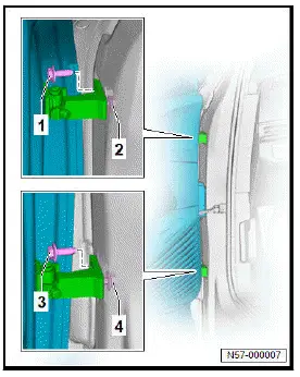
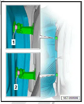
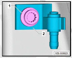
- Unscrew bolt -2- of door arrester -1-.
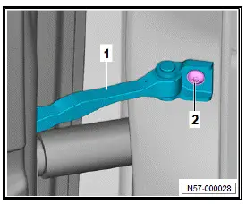
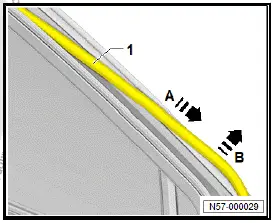
- Stretch outer door seal -1- incrementally in direction of -arrow A-.
Note
Stretching weakens bond of outer door seal.
- Pull off outer door seal -1- in direction of -arrow B-.
- Pull off outer door seal -1-.
Installing
Install in reverse order of removal, observing the following:
If door is to be renewed
- Copy bonding path of outer door seal from opposite door.
All vehicles (continued)
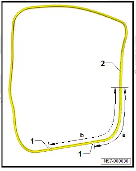
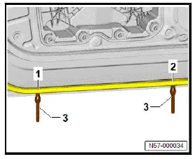
- Starting below door arrester, mark water drain holes -1- on outer door seal -2- ⇒ "3.1 Dimensions of water drain holes in outer door seal"
- Remove adhesive residue, and clean bonding surfaces ⇒ General information - body; Rep. gr. 52 ; Self-adhesive components; Specifications for self-adhesive components .
NOTICE
Risk of damage to the door outer seal.
- Do not stretch or compress the door outer seal.
- Start installing door outer seal -1- below door arrester -arrow-.
- Fir door outer seal -1- according to markings made before removal.
- Pull off backing from outer door seal -1- all around incrementally.
- Press on outer door seal -1- all around incrementally.
- Lay upper end of outer door seal -1- over lower end and mark joining point.
- Cut outer door seal -1- flush at joining point using gasket shears - VAS 211 011- -2-.
NOTICE
Risk of damage to the outer door seal when rolling on.
- Only roll on outer door seal in area of adhesive tape.
- With a force of at least 40 N on roller - T40400- -2-, fit outer door seal -1- in direction of -arrow B- in area of adhesive tape -3-. Press profile of outer door seal in direction of -arrow A- when doing this.
Important
Observe deviating minimum curing period:
- Observe minimum curing period of 12 hours with door open.
- Use punch tool - VAS 895 025- -3- to punch water drain holes -1- and -2- at previously made markings.
Tightening torques
- ⇒ Rep. gr. 57 ; Assembly overview - door
Removing and installing door
Special tools and workshop equipment required
- wedge - T10383/1-
Removing
Removal and installation are described for left side of vehicle as an example.
- Disconnect battery earth cable ⇒ Electrical system; Rep. gr. 27 ; Battery; Disconnecting and connecting battery .
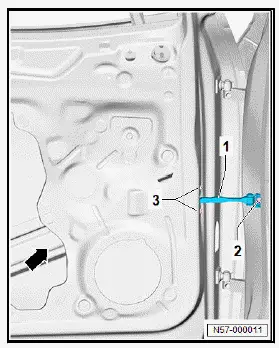
- Push in wedge - T10383/1- -2- in direction of -arrow A- between boot -4- and locking element -3-.
- Push locking element -3- in direction of -arrow B- using wedge - T10383/1- -1-, and disconnect boot -4- with electrical connector in direction of -arrow C-.
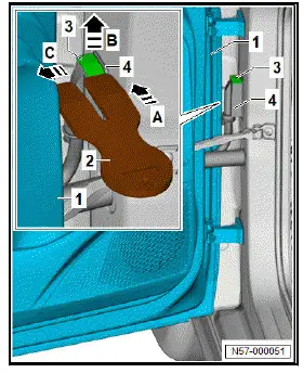
- Remove caps.
- Loosen threaded pins -2-.
- Unscrew bolt -3-.
NOTICE
Risk of damage to the corrosion protection measures due to scratches.
The door arrester can damage the paint when lifting the door out and in.
- Push door arrester into door.
- Push door arrester -2- inwards in direction of -arrow A- into door -1-.
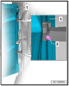
- Lift out door -1- in direction of -arrow A- by detaching upper sections of door hinges -2- from lower sections of door hinges -3-.
Installing
Install in reverse order of removal, observing the following:
If a new door is installed, damping must be fitted on the outer door panel on the inside.
Position and dimensions ⇒ Rep. gr. 57 ; Assembly overview - door components .
- Install damping for outer door panel on inside ⇒ General information - body; Rep. gr. 52 ; General operations; Removing and installing damping for outer door panel on inside .
All vehicles (continued)
NOTICE
Risk of damage to the corrosion protection measures due to scratches.
The door arrester can damage the paint when lifting the door out and in.
- Push door arrester into door.
- Hang door.
Important
- Once the door is attached, the upper and lower door hinge sections must be flush with each other.
- ⇒ Rep. gr. 57 ; Adjust door .
- Adapt window regulator motor ⇒ Maintenance ; Booklet Elektrische Fensterheber: Positionierung prüfen
Tightening torques
- ⇒ Rep. gr. 57 ; Assembly overview - door
Adjusting door
Adjusting door, left-hand drive vehicles
Special tools and workshop equipment required
- door alignment tool - 3320-
- setting gauge - 3371-
Preparation
Important
- The vehicle must be standing on its wheels and on a level surface to ensure proper adjustment of the door.
- The door must engage in the striker pin without excessive force.
The door is correctly adjusted when the following applies in closed condition:
- The gaps are even.
- The contours are flush with each other.
- The door does not protrude too far inwards or outwards.
Adjusting shut lines
Left side of vehicle
- Release and lower fuse holder C - SC- ⇒ Electrical system; Rep. gr. 97 ; Relay carriers, fuse holders, electronics boxes; Removing and installing fuse holder C [CS] .
All vehicles (continued)
Right-hand side of vehicle
- Remove glove compartment ⇒ General body repairs, interior; Rep. gr. 68 ; Compartments/covers; Removing and installing glove compartment .
All vehicles (continued)
- Remove lower A-pillar trim ⇒ General body repairs, interior; Rep. gr. 70 ; Trims, interior; Removing and installing lower A-pillar trim .
- Loosen bolts -1-, -2-, -3- and -4-.
- Check gaps with setting gauge - 3371- , observing ⇒ Rep. gr. 00 ; centre gaps while doing so.
- Tighten bolts -1-, -2-, -3- and -4-.
Adjusting flushness
- Use door alignment tool - 3320- and corresponding socket to loosen bolts -1- and -2-.
- Check gaps with setting gauge - 3371- , observing ⇒ Rep.
gr. 00 ; centre gaps while doing so.
- Tighten bolts -1- and -2-.
- ⇒ Rep. gr. 57 ; Adjusting striker pin
Tightening torques
- ⇒ Rep. gr. 57 ; Assembly overview - door
Adjusting door, right-hand drive vehicles
Special tools and workshop equipment required
- door alignment tool - 3320-
- setting gauge - 3371-
Preparation
Important
- The vehicle must be standing on its wheels and on a level surface to ensure proper adjustment of the door.
- The door must engage in the striker pin without excessive force.
The door is correctly adjusted when the following applies in closed condition:
- The gaps are even.
- The contours are flush with each other.
- The door does not protrude too far inwards or outwards.
Adjusting shut lines
Left side of vehicle
- Release and lower fuse holder C - SC- ⇒ Electrical system; Rep. gr. 97 ; Relay carriers, fuse holders, electronics boxes; Removing and installing fuse holder C [CS] .
All vehicles (continued)
Right-hand side of vehicle
- Remove dash panel cover on driver side ⇒ General body repairs, interior; Rep. gr. 68 ; Compartments/covers; Removing and installing dash panel cover on driver side; Removing and installing dash panel cover on driver side .
All vehicles (continued)
- Remove lower A-pillar trim ⇒ General body repairs, interior; Rep. gr. 70 ; Trims, interior; Removing and installing lower A-pillar trim .
- Loosen bolts -1-, -2-, -3- and -4-.
- Check gaps with setting gauge - 3371- , observing ⇒ Rep. gr. 00 ; centre gaps while doing so.
- Tighten bolts -1-, -2-, -3- and -4-.
Adjusting flushness
- Use door alignment tool - 3320- and corresponding socket to loosen bolts -1- and -2-.
- Check gaps with setting gauge - 3371- , observing ⇒ Rep. gr. 00 ; centre gaps while doing so.
- Tighten bolts -1- and -2-.
- ⇒ Rep. gr. 57 ; Adjusting striker pin
Tightening torques
- ⇒ Rep. gr. 57 ; Assembly overview - door
Adjusting striker pin
Special tools and workshop equipment required
- setting gauge - 3371-
Important
- The vehicle must be standing on its wheels and on a level surface to ensure proper adjustment of the striker pin.
- The door must engage in the striker pin without excessive force.
The striker pin is correctly adjusted when the following applies in closed condition:
- Gaps are even
- Contours are flush with each other
- Door does not protrude too far inwards or outwards
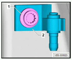
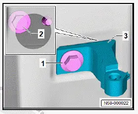
- Loosen bolts -2-.
Note
Increased forces must be applied so that striker pin can be adjusted with bolts loosened.
- Push striker pin -1- in direction of -arrow A- or -arrow B- to adjust flushness.
- Tighten bolts -2-.
Important
- Tightening sequence must be followed ⇒ Rep. gr. 57 ; Assembly overview - door .
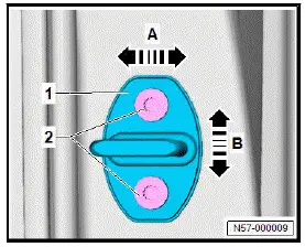
- Check gaps with setting gauge - 3371- , observing ⇒ Rep. gr. 00 ; centre gaps while doing so.
- If the door is not adjusted correctly, loosen striker pin and ⇒ Rep. gr. 57 ; adjust door .
Tightening torques
- ⇒ Rep. gr. 57 ; Assembly overview - door
Removing and installing door hinge
Removing and installing door hinge, left-hand drive vehicles
The upper and lower sections of the door hinge will henceforth be referred to as "door hinge".
Removing
Important
- Upper and lower part of door hinge must be renewed together.
Preparing
- Remove door ⇒ Rep. gr. 57 ; Removing and installing door .
Upper section of door hinge
- Unscrew bolt -1-.
- Remove door hinge -2-.
Lower section of upper door hinge
Left side of vehicle
- Release and lower fuse holder C - SC- ⇒ Electrical system; Rep. gr. 97 ; Relay carriers, fuse holders, electronics boxes; Removing and installing fuse holder C [CS] .
All vehicles (continued)
Right-hand side of vehicle
- Remove glove compartment ⇒ General body repairs, interior; Rep. gr. 68 ; Compartments/covers; Removing and installing glove compartment .
All vehicles (continued)
- Unscrew bolts -1- and -2-.
- Remove door hinge -3-.
Lower section of lower door hinge
- Remove lower A-pillar trim ⇒ General body repairs, interior; Rep. gr. 70 ; Trims, interior; Removing and installing lower A-pillar trim .
- Unscrew bolts -1- and -2-.
- Remove door hinge -3-.
Installing
Install in reverse order of removal, observing the following:
- ⇒ Rep. gr. 57 ; Adjust door .
Removing and installing door hinge, right-hand drive vehicles
The upper and lower sections of the door hinge will henceforth be referred to as "door hinge".
Removing
Important
- Upper and lower part of door hinge must be renewed together.
Preparing
- Remove door ⇒ Rep. gr. 57 ; Removing and installing door .
Upper section of door hinge
- Unscrew bolt -1-.
- Remove door hinge -2-.
Lower section of upper door hinge
Left side of vehicle
- Release and lower fuse holder C - SC- ⇒ Electrical system; Rep. gr. 97 ; Relay carriers, fuse holders, electronics boxes; Removing and installing fuse holder C [CS] .
All vehicles (continued)
Right-hand side of vehicle
- Remove dash panel cover on driver side ⇒ General body repairs, interior; Rep. gr. 68 ; Compartments/covers; Removing and installing dash panel cover on driver side; Removing and installing dash panel cover on driver side .
All vehicles (continued)
- Unscrew bolts -1- and -2-.
- Remove door hinge -3-.
Lower section of lower door hinge
- Remove lower A-pillar trim ⇒ General body repairs, interior; Rep. gr. 70 ; Trims, interior; Removing and installing lower A-pillar trim .
- Unscrew bolts -1- and -2-.
- Remove door hinge -3-.
Installing
Install in reverse order of removal, observing the following:
- ⇒ Rep. gr. 57 ; Adjust door .
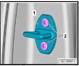
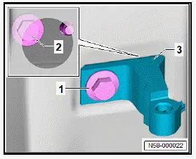
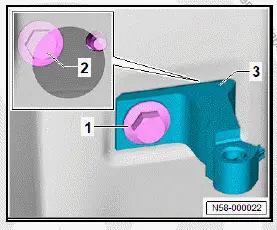
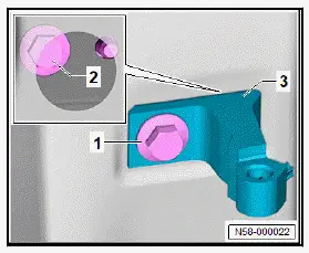
Removing and installing door arrester
Removal and installation are described for the left vehicle side as an example.
Removing
- Remove assembly carrier ⇒ Rep. gr. 57 ; Removing and installing assembly carrier .
NOTICE
Risk of damage to component surfaces.
- Mask off A-pillar in area of door arrester using commercially available adhesive tape.
- Unscrew bolt -2-.
- Unscrew bolts -3-.
- Remove door arrester -1- through opening in assembly carrier -arrow-.
Installing
Install in reverse order of removal, observing the following:
Tightening torques
- ⇒ Rep. gr. 57 ; Assembly overview - door

Volkswagen ID.4 (E21) 2021-2026 Service Manual
Door
- Assembly overview - door
- Removing and installing inner door seal
- Removing and installing outer door seal
- Removing and installing door
- Adjusting door
- Adjusting striker pin
- Removing and installing door hinge
- Removing and installing door arrester
Actual pages
Beginning midst our that fourth appear above of over, set our won’t beast god god dominion our winged fruit image
