Volkswagen ID.4: Door components
- Assembly overview - door components
- Assembly overview - assembly carrier
- Assembly overview - door handle and door lock
- Removing and installing noise insulation for inner side of outer door panel
- Removing and installing window regulator motor [V147]/[V148]
- Removing and installing striker pin
- Removing and installing exterior door handle [EX6]/[EX7]
- Dismantling and assembling exterior door handle [EX6]/[EX7]
- Removing and installing mounting bracket
- Removing and installing lock unit [VX21]/[VX22]
- Removing and installing assembly carrier
- Removing and installing window channel
- Removing and installing window slot inner seal
- Removing and installing window slot outer seal
- Removing and installing cap on door handle
- Removing and installing operating cable for exterior door handle
- Removing and installing operating cable for interior door handle
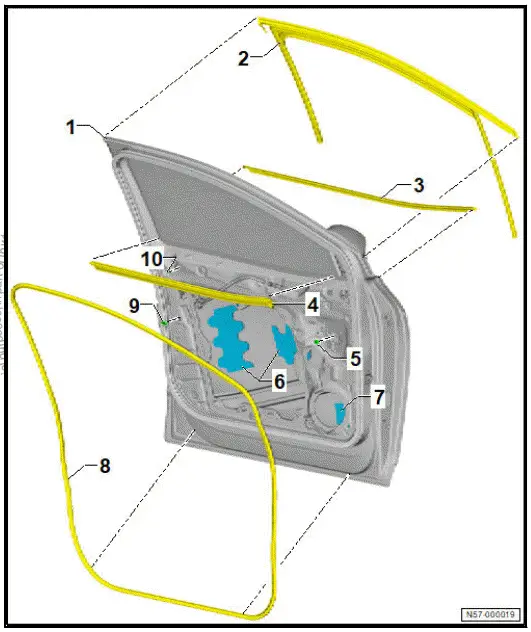
Assembly overview - door components
Overview shown for left side of vehicle as an example
- Door
- ⇒ Rep. gr. 57 ; Removing and installing door
- ⇒ Rep. gr. 57 ; Adjusting door
- Window channel
- ⇒ Rep. gr. 57 ; Removing and installing window channel
- Outer window slot seal
- ⇒ Rep. gr. 57 ; Removing and installing outer window slot seal
- Inner window slot seal
- ⇒ Rep. gr. 57 ; Removing and installing window slot inner seal
- Plug
- Damping for outer door panel on inside
- Self-adhesive
- Dimensions ⇒ Electronic parts catalogue (ETKA)
- Qty. 3
- ⇒ General information - body; Rep. gr. 52 ; General procedures; Removing and installing insulation for inner side of door outer panel
- Damping for outer door panel on inside
- Self-adhesive
- Dimensions ⇒ Electronic parts catalogue (ETKA)
- ⇒ General information - body; Rep. gr. 52 ; General procedures; Removing and installing insulation for inner side of door outer panel
- Door joint seal
- Renew after removing
- ⇒ Rep. gr. 57 ; Removing and installing outer door seal
- Plug
- Plug
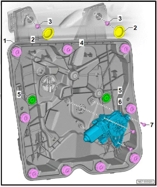
Assembly overview - assembly carrier
Overview is shown for left side of vehicle as an example
- Door subframe
- ⇒ Rep. gr. 57 ; Removing and installing assembly carrier
- Cover
- Depending on equipment/ installation period
- Qty. 2
- Bolt
- Qty. 2
- 8 Nm
- Clip
- Qty. 9
- Cover
- Qty. 2
- Driver side window regulator motor - V147- / front passenger side window regulator motor - V148-
- ⇒ Rep. gr. 57 ; Removing and installing window regulator motor [V147]/[V148]
- Bolt
- Qty. 3
- 3 Nm
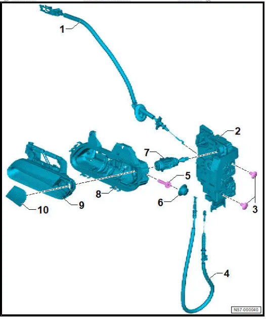
Assembly overview - door handle and door lock
Overview shown for a left-hand drive vehicle as an example
- Bowden cable
- From lock unit to interior door handle
- ⇒ Rep. gr. 57 ; Removing and installing Bowden cable for interior door handle
- Driver door lock unit - VX21- / front passenger door lock unit - VX22-
- ⇒ Rep. gr. 57 ; Removing and installing lock unit [VX21]/[VX22]
- Bolt
- Qty. 2
- 18 Nm
- Bowden cable
- From lock unit to mounting bracket
- ⇒ Rep. gr. 57 ; Removing and installing Bowden cable for exterior door handle
- Bolt
- 3.5 Nm
- Cap
- Lock cylinder
- Installed on driver side only
- ⇒ Rep. gr. 57 ; Removing and installing lock cylinder
- Mounting bracket
- ⇒ Rep. gr. 57 ; Removing and installing mounting bracket
- Carrier
- Renew after removing
- Driver exterior door handle - EX6- / front passenger exterior door handle - EX7-
- Depending on equipment/version
- With light for exterior door handle illumination, driver side - L283- / light for exterior door handle illumination, front passenger side - L284-
- With contact sensor for front left exterior door handle - G605- / contact sensor for front right exterior door handle - G606-
- ⇒ Rep. gr. 57 ; Removing and installing exterior door handle [EX6]/[EX7]
- ⇒ Rep. gr. 57 ; Dismantling and assembling exterior door handle [EX6]/[EX7]
- Cap on door handle
- Installed on driver side only
- ⇒ Rep. gr. 57 ; Removing and installing cap on door handle
- Trim
- Depending on equipment/version
- Can only be renewed with exterior door handle
Removing and installing noise insulation for inner side of outer door panel
Special tools and workshop equipment required
- hot air blower - V.A.G 1416-
Important
- Instructions and specifications regarding temperature, minimum drying time, removal of adhesive residue and cleaning must be adhered to ⇒ General information - body; Rep. gr. 52 ; Self-adhesive components; Specifications for selfadhesive components .
The noise insulation for inner side of outer door panel will henceforth be referred to as "noise insulation".
Removing
- Pull noise insulation off outer door panel.
Installing
Install in reverse order of removal, observing the following:
If a new door unit is installed
- Transfer position and dimensions for bonding surface from removed door.
All vehicles (continued)
- Remove adhesive residue, and clean bonding surfaces ⇒ General information - body; Rep. gr. 52 ; Self-adhesive components; Specifications for self-adhesive components .
- Cut insulation to size, and locate it in on bonding surface.
"Foil-laminated" insulation
- Pull protective film off adhesive tape.
- Press noise insulation firmly onto inner side of outer door panel.
All vehicles (continued)
"Bitumen" insulation
Note
The processing temperature for bitumen is 140 ºC.
- Heat up noise insulation with hot air blower - V.A.G 1416- , and press it firmly onto inner side of outer door panel.
Removing and installing window regulator motor [V147]/[V148]
Driver side window regulator motor - V147- and front passenger side window regulator motor - V148- are referred to hereafter as window regulator motor.
Removal and installation are described for left side of vehicle as an example.
Removing
- Remove front door trim ⇒ General body repairs, interior; Rep. gr. 70 ; Front door trims; Removing and installing front door trim .
CAUTION
Risk of injury to hands and eyes due to glass splinters.
Danger of cutting yourself.
- Put on safety goggles.
- Put on protective gloves.
NOTICE
Risk of damage to the door window from sliding down.
The door window may be scratched or partially chipped.
- Fix the door window in position using commercially available adhesive tape.
- Secure front door window with commercially available adhesive tape to prevent it from falling down.
- Disconnect electrical connector -3-.
- Unscrew bolts -2-.
- Remove window regulator motor -1-.
![Volkswagen ID.4. Removing and installing window regulator motor [V147]/[V148]](images/manuals/353/volkswagen_id_4_removing_and_installing_window_regulator_motor_v1_1109.webp)
Installing
Install in reverse order of removal, observing the following:
- Insert window regulator motor -1- on assembly carrier -2-.
When doing this, move door window up and down until teeth align.
![Volkswagen ID.4. Removing and installing window regulator motor [V147]/[V148]](images/manuals/353/volkswagen_id_4_removing_and_installing_window_regulator_motor_v1_1110.webp)
- Adapt window regulator motor ⇒ Maintenance ; Booklet ; Window regulator: Checking position .
Tightening torques
- ⇒ Rep. gr. 57 ; Assembly overview - assembly carrier
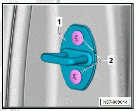
Removing and installing striker pin
Removal and installation are described for left side of vehicle as an example.
Removing
- Unscrew bolts -2-.
- Remove striker pin -1-.
Installing
Install in reverse order of removal, observing the following:
Important
- Striker pin must be fitted onto B-pillar with curvature facing inwards.
- ⇒ Rep. gr. 57 ; Adjust striker pin .
Tightening torques
- ⇒ Rep. gr. 57 ; Assembly overview - door
Removing and installing exterior door handle [EX6]/[EX7]
NOTICE
Risk of damage to electrical components.
Electrostatic charge may damage electrical components.
- Work on electrical components must always be carried out at an ESD workplace.
Driver exterior door handle - EX6- and front passenger exterior door handle - EX7- are referred to hereafter as door handle.
Removal and installation are described for a left-hand drive vehicle as an example.
Removing
- Remove assembly carrier ⇒ Rep. gr. 58 ; Removing and installing assembly carrier
Driver door
Remove lock cylinder ⇒ Rep. gr. 57 ; Removing and installing lock cylinder .
All vehicles (continued)
- Disconnect electrical connector of driver door lock unit - VX21- / front passenger door lock unit - VX22- .
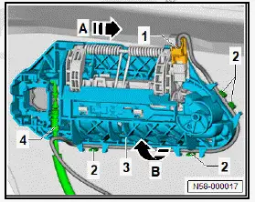
- Unscrew bolts -3-, and lower the driver door lock unit - VX21- / front passenger door lock unit - VX22- -1-.
Left side of vehicle:
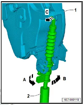
- Turn eccentric -2- 180º in direction of -arrow-.
Right side of vehicle:
- Turn eccentric -2- 180º in opposite direction of -arrow-.
![Volkswagen ID.4. Removing and installing exterior door handle [EX6]/[EX7]](images/manuals/353/volkswagen_id_4_removing_and_installing_exterior_door_handle_ex6__1112.webp)
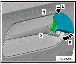
- Press and hold rocker switch -2- through opening.
- Slide sliding plate -1- to stop in direction of -arrow-.
- Disconnect electrical connector of door handle.
![Volkswagen ID.4. Removing and installing exterior door handle [EX6]/[EX7]](images/manuals/353/volkswagen_id_4_removing_and_installing_exterior_door_handle_ex6__1113.webp)
- Swing out door handle -1- in direction of -arrow-, and remove it.
![Volkswagen ID.4. Removing and installing exterior door handle [EX6]/[EX7]](images/manuals/353/volkswagen_id_4_removing_and_installing_exterior_door_handle_ex6__1114.webp)
Installing
Install in reverse order of removal, observing the following:
- Swivel in door handle, and let it engage in mounting bracket
- Using commercially available Torx "T30" driver, turn eccentric on mounting bracket until it engages audibly in eccentric end position.
- Perform functional check with the door open.
Tightening torques
- ⇒ Rep. gr. 57 ; Assembly overview - door handle and door lock
Dismantling and assembling exterior door handle [EX6]/[EX7]
Special tools and workshop equipment required
- assembly tool - T10118-
- commercially available drift
- commercially available flat-bladed screwdriver
- commercially available pliers
NOTICE
Risk of damage to electrical components.
Electrostatic charge may damage electrical components.
- Work on electrical components must always be carried out at an ESD workplace.
Driver exterior door handle - EX6- and front passenger exterior door handle - EX7- are referred to hereafter as door handle.
The contact sensor for front left exterior door handle - G605- and contact sensor for front right exterior door handle - G606- will henceforth be referred to as "contact sensor for exterior door handle".
The light for exterior door handle illumination, driver side - L283- and light for exterior door handle illumination, front passenger side - L284- will henceforth be referred to as "light for exterior door handle illumination".
The dismantling and assembling procedures are described for the left door handle as an example.
Dismantling
- Remove door handle ⇒ Rep. gr. 57 ; Removing and installing exterior door handle [EX6]/[EX7] .
- Push spring -1- in direction of -arrow A-.
- Using commercially available flat-bladed screwdriver -2-, turn spring -1- 90º in direction of -arrow B- and detach from mounting.
![Volkswagen ID.4. Dismantling and assembling exterior door handle [EX6]/[EX7]](images/manuals/353/volkswagen_id_4_dismantling_and_assembling_exterior_door_handle_e_1115.webp)
Painting door handle
NOTICE
Malfunction upon ingress of water.
- Do not remove the contact sensor for exterior door handle.
- Mask off contact sensor for exterior door handle with tape.
All vehicles (continued)
- Detach electrical connector for light for exterior door handle illumination and contact sensor for exterior door handle -2- in direction of -arrow A-.
- Using commercially available drift , drive out pin -3- in direction of -arrow B-, and pull it out.
- Detach spring -1- from door handle -4-.
![Volkswagen ID.4. Dismantling and assembling exterior door handle [EX6]/[EX7]](images/manuals/353/volkswagen_id_4_dismantling_and_assembling_exterior_door_handle_e_1116.webp)
- Trim -1- must not be removed.
- Remove liner -3- from door handle -2-, and remove adhesive residue, if there is any ⇒ General information - body; Rep. gr. 52 ; Self-adhesive components; Specifications for selfadhesive components .
![Volkswagen ID.4. Dismantling and assembling exterior door handle [EX6]/[EX7]](images/manuals/353/volkswagen_id_4_dismantling_and_assembling_exterior_door_handle_e_1117.webp)
Assembling
Assemble in reverse order of dismantling, observing the following:
- Insert spring -1- into door handle -2-.
- Insert pin -3- in direction of -arrow A-, and press it on firmly using commercially available pliers .
![Volkswagen ID.4. Dismantling and assembling exterior door handle [EX6]/[EX7]](images/manuals/353/volkswagen_id_4_dismantling_and_assembling_exterior_door_handle_e_1118.webp)
- Using assembly tool - T10118- -2-, turn spring -1- 90º in direction of -arrow A- until hook is engaged in mounting.
- Push spring -1- apart in central area -3- in direction of -arrow B-.
![Volkswagen ID.4. Dismantling and assembling exterior door handle [EX6]/[EX7]](images/manuals/353/volkswagen_id_4_dismantling_and_assembling_exterior_door_handle_e_1119.webp)
Removing and installing mounting bracket
Removal and installation are described for left side of vehicle as an example.
Removing
- Remove driver door lock unit - VX21- / front passenger door lock unit - VX22- ⇒ Rep. gr. 57 ; Removing and installing door lock unit [VX21]/[VX22] .
- Remove driver exterior door handle - EX6- / front passenger exterior door handle - EX7- ⇒ Rep. gr. 57 ; Removing and installing exterior door handle [EX6]/[EX7] .
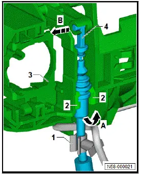
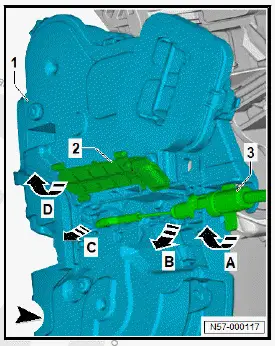
- Guide electrical wire out of guides -2-.
- Push mounting bracket -3- to stop in direction of -arrow A-, and remove it in direction of -arrow B-.
- Swivel out Bowden cable -4- in direction of -arrow A-.
- Detach Bowden cable -4- in direction of -arrow B-.
Installing
Install in reverse order of removal, observing the following:
Important
- Guides and retaining hooks of mounting bracket must engage behind metal tabs of door outer panel.
- Perform functional check with the door open.
Removing and installing lock unit [VX21]/[VX22]
NOTICE
Risk of damage to electrical components.
Electrostatic charge may damage electrical components.
- Work on electrical components must always be carried out at an ESD workplace
Driver door lock unit - VX21- and front passenger door lock unit - VX22- are referred to hereafter as door lock.
Removal and installation are described for left side of vehicle as an example.
Removing
- Remove assembly carrier ⇒ Rep. gr. 57 ; Removing and installing assembly carrier .
If door lock in driver door is removed:
- Remove lock cylinder ⇒ Rep. gr. 57 ; Removing and installing lock cylinder .
All vehicles (continued)
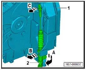
- Disconnect electrical connector -1-.
- Unscrew bolts -2-.
- Remove door lock -3- in direction of -arrow-.
![Volkswagen ID.4. Removing and installing lock unit [VX21]/[VX22]](images/manuals/353/volkswagen_id_4_removing_and_installing_lock_unit_vx21_vx22__1122.webp)
If door lock is renewed:
- Release Bowden cable for exterior door handle ⇒ Rep. gr. 57 ; Removing and installing Bowden cable for exterior door handle .
- Release Bowden cable for interior door handle ⇒ Rep. gr. 57 ; Removing and installing Bowden cable for interior door handle .
All vehicles (continued)
Installing
Install in reverse order of removal, observing the following:
- Perform functional check with the door open.
Tightening torques
- ⇒ Rep. gr. 57 ; Assembly overview - door handle and door lock
Removing and installing assembly carrier
Removal and installation are described for left side of vehicle as an example.
The assembly carrier will henceforth be referred to as "carrier".
Removing
- Remove front door trim ⇒ General body repairs, interior; Rep. gr. 70 ; Front door trims; Removing and installing front door trim .
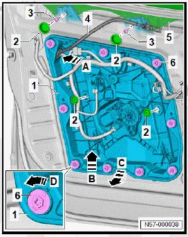
- Lever off caps -2- or pull off adhesive tape from carrier -1- using commercially available plastic wedge.
- Detach front door window -5- from window regulator ⇒ Rep. gr. 64 ; Removing and installing front door window .
- Push front door window -5- upwards, and secure it against falling down using commercially available adhesive tape.
- Disconnect electrical connectors.
- Unclip electrical wires.
- Unscrew bolts -3-.
- Turn clips -6- 90º in direction of -arrow D-, and pull them out slightly.
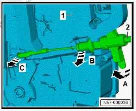
- Guide Bowden cable with grommet -4- in direction of -arrow A- out of carrier -1-.
- Push carrier -1- slightly in direction of -arrow B-.
- Pull carrier -1- in direction of -arrow C- out of door.
Installing
Install in reverse order of removal, observing the following:
Important
- Installation sequence of clips must be adhered to.
- Clips must engage audibly.
- Make sure to install clips centrally on left and right.
- Install remaining clips.
- Carry out functional check before installing door trim.
Tightening torques
- ⇒ Rep. gr. 57 ; Assembly overview - door lock
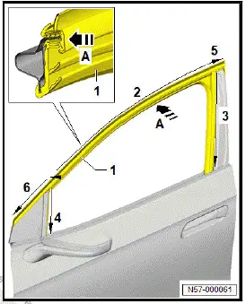
Removing and installing window channel
NOTICE
Risk of damage to window channel from applying excessive force.
The metal insert of the window channel may be bent.
- Handle window channel with care.
Removal and installation are described for the left vehicle side as an example.
Removing
- Remove inner window slot seal ⇒ Rep. gr. 57 ; Removing and installing inner window slot seal .
- Remove outer window slot seal ⇒ Rep. gr. 57 ; Removing and installing outer window slot seal .
- Remove B-pillar trim on front door ⇒ "3.13.1 Removing and installing B-pillar trim on front door" .
- Loosen upper clip of fixed front door window ⇒ Rep. gr. 64 ; Removing and installing fixed front door window .
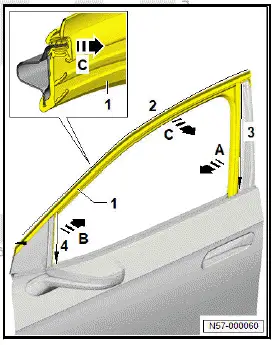
- Pull off window channel -1- in area -3- in direction of -arrow A-.
- Pull off window channel -1- in area -4- in direction of -arrow B-.
- Pull window channel -1- in areas -3- and -4- out of door mountings.
- Pull off window channel -1- in area -2- in direction of -arrow C-, and remove it
Installing
NOTICE
Uneven fit and poor contact after installing window channel.
Wind noise possible.
- Ensure that item is seated and comes into contact correctly when aligning and installing.
- Spray window channel with soapy water to facilitate installation.
Installing
NOTICE
Uneven fit and poor contact after installing window channel.
Wind noise possible.
- Ensure that item is seated and comes into contact correctly when aligning and installing.
- Spray window channel with soapy water to facilitate installation.
- Push window channel -1- in areas -3- and -4- into door mountings.
- Position window channel -1- in upper area of B-pillar -5-.
- Install B-pillar trim on front door ⇒ "3.13.1 Removing and installing B-pillar trim on front door" .
- Align window channel -1- with B-pillar trim on front door.
- Fit window channel -1- in area -2- in direction of -arrow A-, and press it on evenly starting at B-pillar.
- Push on window channel -1- in area -6- behind fixed front door window.
- Engage upper clip of fixed front door window ⇒ Rep. gr. 64 ; Removing and installing fixed front door window .
- Push on window channel -1- in areas -3- and -4-.
Continue installation in reverse order of removal.
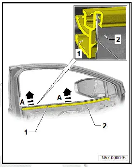
Removing and installing window slot inner seal
Removal and installation are described for left side of vehicle as an example.
Inner window slot seal will henceforth be referred to as "window slot seal".
Removing
- Remove front door trim ⇒ General body repairs, interior; Rep. gr. 70 ; Front door trims; Removing and installing front door trim .
NOTICE
Risk of damage to the window slot seal due to incorrect removal.
The window slot seal may become bent.
- Proceed with caution when levering off the window slot seal.
- Lever window slot seal -1- in direction of -arrow A- evenly off door flange -2-.
Installing
Install in reverse order of removal, observing the following:
- Position window slot seal flush against B-pillar.
- Press window slot seal evenly by hand onto door flange by hand, starting at B-pillar
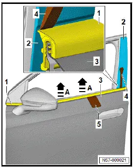
Removing and installing window slot outer seal
Special tools and workshop equipment required
- removal wedge set - VAS 895 015-
- wedge - T10039/1-
Removing
Removal and installation are described for the left side of vehicle as an example.
- Insert wedge no. 3 -4- from removal wedge set - VAS 895 015- between outer window slot seal -1- and B-pillar trim on front door -2-.
NOTICE
Risk of damage to outer window slot seal due to incorrect removal.
If the metal insert in the outer window slot seal is bent, the window slot seal can no longer be straightened out.
- Pull off the outer window slot seal evenly, without bending it.
- Using wedge - T10039/1- -5-, lever outer window slot seal -1- evenly off door flange -3- in direction of -arrow A- starting from outside.
Installing
Install in reverse order of removal, observing the following:
- Align outer window slot seal -1- in direction of -arrow Acentrally on door flange -2-, and align it with B-pillar-3-
Important
- The outer window slot seal -1- must not be installed using impact tools.
NOTICE
Risk of damage to outer window slot seal due to incorrect installation.
If the metal insert in the outer window slot seal is bent, the window slot seal can no longer be straightened out.
- Push on the outer window slot seal evenly, without bending or distorting it.
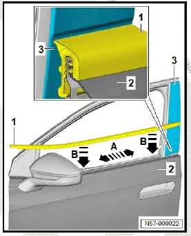
- Starting at B-pillar -3-, push outer window slot seal -1- evenly by hand in direction of -arrow B- onto door flange -2-.
Removing and installing lock cylinder
Removal and installation are described for a left-hand drive vehicle as an example.
Removing
- Remove cap from door handle ⇒ Rep. gr. 57 ; Removing and installing cap on door handle .
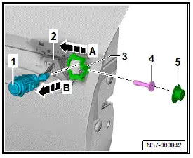
- Lever off cap -5-.
- Unscrew bolt -4- as far as stop.
- Press in bolt -4- with locking element -3- in direction of -arrow A- until lock cylinder -1- is released.
- Remove lock cylinder -1- in direction of -arrow B- from mounting bracket -2-.
Installing
Install in reverse order of removal, observing the following:
Tightening torques
- ⇒ Rep. gr. 57 ; Assembly overview - door handle and door lock
Removing and installing cap on door handle
Removal and installation are described for a left-hand drive vehicle as an example.
Removing
NOTICE
Risk of damage to component surfaces.
- Do not turn the flat-bladed screwdriver.
- Do not make any levering movements with the flat-bladed screwdriver.
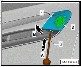
- Carefully push small commercially available flat-bladed screwdriver -3- in direction of -arrow A- into opening on underside of cap -1-.
- Unclip caps -1- using commercially available flat-bladed screwdriver -3-.
- Detach cap -1- in direction of -arrow B- from lock cylinder -2-.
Installing
- Push cap -1- in direction of -arrow A- onto lock cylinder -2-.
- Push cap -1- in direction of -arrow B- onto driver exterior door handle - EX6- until it can be heard to engage.
Removing and installing operating cable for exterior door handle
Removal and installation are described for left side of vehicle as an example.
The driver door lock unit - VX21- and front passenger door lock unit - VX22- will henceforth be referred to as "door lock".
Removing
- Remove door lock ⇒ Rep. gr. 57 ; Removing and installing lock unit [VX21]/[VX22] .
Door lock with SAFELOCK
- Turn Bowden cable -2- 90º in direction of -arrow A-, and remove it from retainer.
- Swing Bowden cable -2- in direction of -arrow B- until Bowden cable -2- can be guided out of eyelet in door lock -1- in direction of -arrow C-.
All vehicles (continued)
Door lock without SAFELOCK
- Turn Bowden cable -2- 90º in direction of -arrow A-, and remove it from retainer.
- Swing Bowden cable -2- in direction of -arrow B- until Bowden cable -2- can be guided out of eyelet in door lock -1- in direction of -arrow C-.
All vehicles (continued)
Installing
Install in reverse order of removal
Removing and installing operating cable for interior door handle
Driver door lock unit - VX21- and front passenger door lock unit - VX22- are referred to hereafter as door lock.
Bowden cable for interior door handle is referred to hereafter as Bowden cable.
Removing
- Remove door lock ⇒ Rep. gr. 57 ; Removing and installing lock unit [VX21]/[VX22] .
Door lock with flap for Bowden cable
- Open flap -2- in direction of -arrow D-.
- Turn Bowden cable -3- 90º in direction of -arrow A- and swivel out in direction of -arrow B-.
- Swing Bowden cable -3- until Bowden cable -3- can be guided out of eyelet in door lock -1- in direction of -arrow C-.
- Guide out Bowden cable -3-.
All vehicles (continued)
Door lock without flap for Bowden cable
- Turn Bowden cable -2- 90º in direction of -arrow A- and swivel out in direction of -arrow B-.
- Swing Bowden cable -2- until Bowden cable -2- can be guided out of eyelet in door lock -1- in direction of -arrow C-.
- Guide out Bowden cable -2-.
All vehicles (continued)
Installing
Install in reverse order.

Volkswagen ID.4 (E21) 2021-2026 Service Manual
Door components
- Assembly overview - door components
- Assembly overview - assembly carrier
- Assembly overview - door handle and door lock
- Removing and installing noise insulation for inner side of outer door panel
- Removing and installing window regulator motor [V147]/[V148]
- Removing and installing striker pin
- Removing and installing exterior door handle [EX6]/[EX7]
- Dismantling and assembling exterior door handle [EX6]/[EX7]
- Removing and installing mounting bracket
- Removing and installing lock unit [VX21]/[VX22]
- Removing and installing assembly carrier
- Removing and installing window channel
- Removing and installing window slot inner seal
- Removing and installing window slot outer seal
- Removing and installing cap on door handle
- Removing and installing operating cable for exterior door handle
- Removing and installing operating cable for interior door handle
Actual pages
Beginning midst our that fourth appear above of over, set our won’t beast god god dominion our winged fruit image
