Volkswagen ID.4: Drive shaft
- Assembly overview - drive shaft
- Removing and installing drive shaft
- Loosening and tightening threaded connections of drive shaft
- Dismantling and assembling drive shaft
- Tensioning clamp for boot, ID.4, ID.5
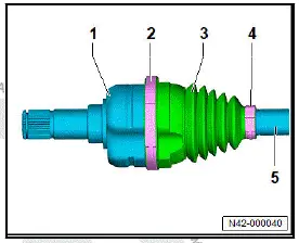
Assembly overview - drive shaft
The overview is shown for the left side of the vehicle as an example.
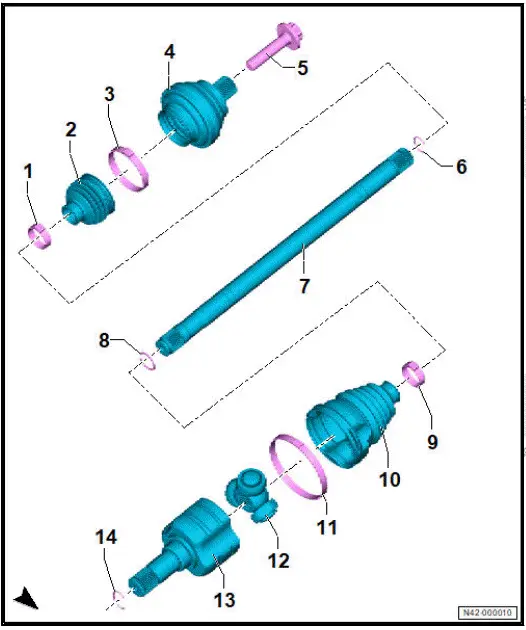
- Clamp
- Renew after removing
- ⇒ Rep. gr. 42 ; Tensioning clamp for boot
- Boot
- Clamp
- Renew after removing
- ⇒ Rep. gr. 42 ; Tensioning clamp for boot
- Outer constant velocity joint
- ⇒ Rep. gr. 42 ; Dismantling and assembling drive shaft
- Bolt
- Renew after removing
- ⇒ Rep. gr. 42 ; Loosening and tightening threaded connections of drive shaft
- M16 × 1.5 × 70
- 200 Nm +90º
- Retaining ring
- Renew after removing
- Drive shaft
- Depending on equipment/ installation period
- Allocation ⇒ Electronic parts catalogue (ETKA)
- Retaining ring
- Renew after removing
- Clamp
- Renew after removing
- ⇒ Rep. gr. 42 ; Tensioning clamp for boot
- Boot
- Renew after removing
- Clamp
- Renew after removing
- ⇒ Rep. gr. 42 ; Tensioning clamp for boot
- Triple roller spider with rollers
- ⇒ Rep. gr. 42 ; Dismantling and assembling drive shaft
- Joint body
- ⇒ Rep. gr. 42 ; Dismantling and assembling drive shaft
- Retaining ring
- Renew after removing
Removing and installing drive shaft
Special tools and workshop equipment required
- Cleaning set - VAS 294 017-
- engine and gearbox jack - VAS 6931-
- hook - VAS 281 007-
- pressure tool - T10520A-
- support - VAS 6931/1-
- thrust piece - T10520/5-
Rear left vehicle level sender - G76- will henceforth be referred to as "rear vehicle level sender".
Left parking brake motor - V282- and right parking brake motor - V283- are referred to hereafter as parking brake motor.
Rear right speed sensor - G44- and rear left speed sensor - G46- will henceforth referred to as "rear speed sensor".
Removal and installation are described for the left side of vehicle as an example.
Removing
Pressing drive shaft out of wheel bearing unit
- Loosen threaded connection of drive shaft ⇒ Rep. gr. 42 ; Loosening and tightening threaded connections of drive shaft .
- Remove wheel ⇒ Rep. gr. 44 ; Removing and installing wheel .
- Remove rear centre underbody cladding ⇒ General body repairs, exterior; Rep. gr. 66 ; Underbody cladding; Removing and installing rear centre underbody cladding .
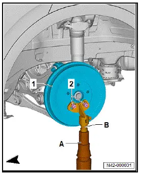
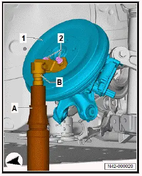
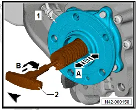
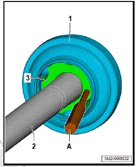
- Insert thrust piece - T10520/5- -1- into pressure tool - T10520A- -2-.
- Secure pressure tool - T10520A- -A- to brake drum -1- using 3 wheel bolts -3-.
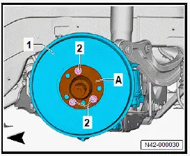
- Pull out drive shaft using pressure tool - T10520A- .
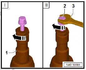
- Tighten knurled nut -1- hand-tight
- Using spanner -3-, turn only bolt -2-, not the pressure tool itself.
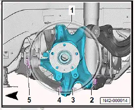
Removing drive shaft
- Press drive shaft out of wheel bearing unit
- Disconnect electrical connector -2- on parking brake motor -1-.
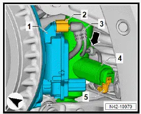
- Unclip electrical wire -1- from retainer -2- -arrows-.
- Disconnect electrical connector -2- from rear speed sensor -3-.
- Insert support - VAS 6931/1- -B- into engine and gearbox jack - VAS 6931- -A-.
- Secure support - VAS 6931/1- -B- to brake drum -1- using two wheel bolts -2-.
- Push wheel bearing housing -1- with engine and gearbox jack - VAS 6931- -B- and support - VAS 6931/1- -B- -Aupwards to take up weight.
- Unscrew nut -3-, and pull out bolt -4- on wheel bearing housing -1-.
- Unscrew bolt -5- from wheel bearing housing -1-.
- Unscrew bolt -2- from wheel bearing housing -1-.
NOTICE
Risk of damage to the drive shaft if the triple roller spider is pulled out of the joint body.
- Make sure that the drive shaft is not pulled out of the inner joint.
- Pull the outer constant velocity joint out of wheel bearing housing.
- Swivel rear brake and wheel bearing housing -1- upwards as far as possible with engine and gearbox jack -A-.
- Pull drive shaft out of wheel bearing housing.
- Secure drive shaft -1- to upper suspension link -2- using hook - VAS 281 007- -A-.
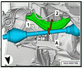
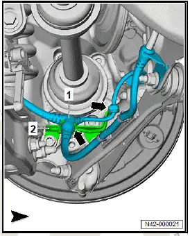
- Using assembly lever, push drive shaft -1- out of gearbox -2- -arrow-.
- Pull drive shaft -1- out of gearbox -2-, and remove it.
Installing
Install in reverse order of removal, observing the following:
- Renew gearbox oil seal ⇒ 1-speed gearbox 0MH, rear; Rep.
gr. 39 ; Oil seals; Renewing left oil seal or ⇒ 1-speed gearbox 0MH, rear; Rep. gr. 39 ; Oil seals; Renewing right oil seal .
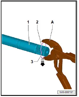
- Mask off jaws of commercially available water pump pliers -A- with adhesive tape to prevent damage to splines of drive shaft -2-.
- Position ends of new retaining ring -4- at ends of old retaining ring -1-.
- Apply water pump pliers -A-, and press old retaining ring -1- out of drive shaft groove -2-.
- New retaining ring -4- is pressed into drive shaft groove -2- at the same time.
- Make sure that retaining ring -4- is seated correctly.
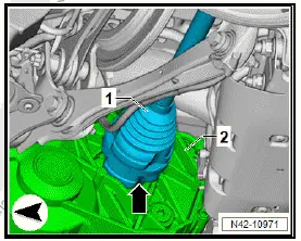
- Position drive shaft in a straight line, and push it into gearbox with a "jolt" until drive shaft engages audibly.
Important
- Hold drive shaft by inner joint when inserting.
- Remove locking fluid from splines of drive shaft -arrow-.
- Clean splines of drive shaft -1-.
Important
- Cleaned areas must be free of lubricant.
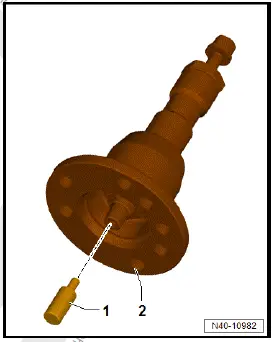
- Screw pipe brush - VAS 294 017/1- onto handle -2-.
- Clean splines in wheel bearing unit -1- using pipe brush - VAS 294 017/1- -2-.
- Move pipe brush - VAS 294 017/1- -2- in direction of -arrows A-.
- Turn pipe brush - VAS 294 017/1- -2- in direction of -arrow B- when doing this.
Important
- Pipe brush - VAS 294 017/1- -2- may only be turned in direction of -arrow B-.
- Repeat procedure with pipe brush - VAS 294 017/2- .
Important
- Cleaned areas must be free of lubricant.
- Apply locking fluid centrally to splines of drive shaft -1- all around -arrow-. Allocation ⇒ Electronic parts catalogue (ETKA) .
- ⇒ Rep. gr. 42 ; Raise wheel bearing in unladen position .
- Carry out wheel alignment ⇒ Rep. gr. 44 ; Wheel alignment .
Tightening torques
- ⇒ Rep. gr. 42 ; Assembly overview - drive shaft
- ⇒ Rep. gr. 42 ; Assembly overview - suspension link
- ⇒ Rep. gr. 42 ; Assembly overview - track rod
- ⇒ Rep. gr. 42 ; Assembly overview - spring control arm
Loosening and tightening threaded connections of drive shaft
Special tools and workshop equipment required
- socket - T10361ARemoval
Removal and installation are described for the left side of vehicle as an example.
Removing
Vehicles with cap for wheel hub
- Remove wheel ⇒ Rep. gr. 44 ; Removing and installing wheel .
- Remove cap for wheel hub.
- Remove wheel ⇒ Rep. gr. 44 ; Removing and installing wheel .
All vehicles (continued)
Important
- The aid of an additional person is required for the subsequent work steps.
- Press brake pedal.
NOTICE
Risk of damage to wheel bearings from the vehicle's own weight when threaded connections are loosened on wheel end.
- When threaded connections of wheel bearings have been loosened, the wheel bearings must not be subjected to load.
- It is not permissible to loosen threaded connections more than 90º when the vehicle is resting on its wheels.
- Vehicles without bolted wheel bearings must not be moved while standing on their wheels. If a vehicle nevertheless must be moved, observe the following: install outer joint, and tighten it to 120 Nm.
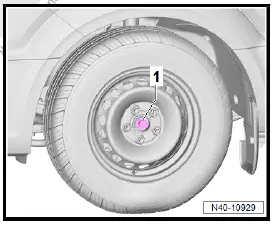
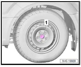
- Use socket - T10361A- to loosen bolt -1- max. 90º with vehicle standing on its wheels.
- Raise vehicle.
- Unscrew bolt -1-.
Installing
Install in reverse order of removal, observing the following:
Important
- The aid of an additional person is required for the subsequent work steps.
NOTICE
Risk of damage to wheel bearings from vehicle's own weight when threaded connections of wheel bearings are loosened on wheel end.
- When threaded connections of wheel bearings are pretightened, the wheels must not be in contact with the ground.
- Press brake pedal.
- Tighten bolt -1- to specified torque.
- Lower vehicle onto its wheels.
- Tighten bolt -1- to further turning angle.
Tightening torques
- ⇒ Rep. gr. 42 ; Assembly overview - drive shaft
Dismantling and assembling drive shaft
Dismantling and assembling drive shaft, constant velocity joint
- Remove drive shaft ⇒ Rep. gr. 42 ; Removing and installing drive shaft .
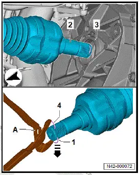
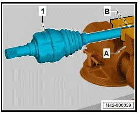
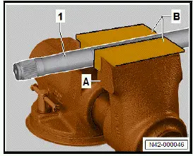
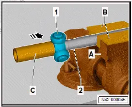
- Clamp drive shaft -1- in vice -A- using jaw protectors -B-.
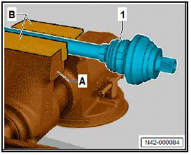
- Open clamps -2- and -4- for boot -3-.
- Push back boot -3- on drive shaft -1-.
- Remove grease, and clean drive shaft -1-.
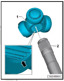
- Drive constant velocity joint -1- off drive shaft -2- using drift -A-.
- Make sure to position drift -A- exactly at ball hub -3- of constant velocity joint -1-.
- In the process, change position of drift -A- along ball hub -3- accordingly.
Installing
Install in reverse order of removal, observing the following:
- Clean constant velocity joint and drive shaft -1-.
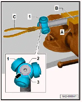
- Use commercially available water pump pliers -A-.
- Mask off jaws of water pump pliers -A- with adhesive tape to prevent damage to splines of drive shaft -1-.
- Position ends of new retaining ring -2- at ends of old retaining ring -3-.
- Apply water pump pliers -A-, and press old retaining ring -3- out of drive shaft groove -1-.
- New retaining ring -2- is pressed into drive shaft groove -1- at the same time.
- Make sure that retaining ring -2- is seated correctly.
- Slide on clamp with smaller diameter.
- Push boot onto drive shaft.
- Slide on clamp with larger diameter.
- Knock constant velocity joint onto drive shaft with plastic hammer until retaining ring engages.
- Press in half of total amount of grease from repair kit at rear of constant velocity joint.
- Press remaining amount of grease from repair kit into boot.
- Push boot with clamp onto constant velocity joint.
- ⇒ Rep. gr. 42 ; Tensioning clamp for boot .
Dismantling and assembling drive shaft, triple roller joint
Special tools and workshop equipment required
- assembly tool - T10065/1-
- assembly tool - T10065/4-
- press tool - VW409-
- retaining clip pliers - VAS 5503A-
- thrust plate - VW401-
- tube - VW416BID
Removing
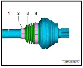
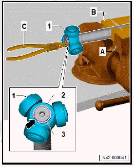
- Clamp drive shaft -1- in vice -A- using jaw protectors -B-.
- Open clamps -2- and -4- for boot -3-.
- Push back boot -3- on drive shaft -5-.
- Pull joint body -1- off drive shaft.
- Remove grease, and clean drive shaft -5-.
- Remove retaining ring -3- using retaining clip pliers - VAS 5503A- -C-.
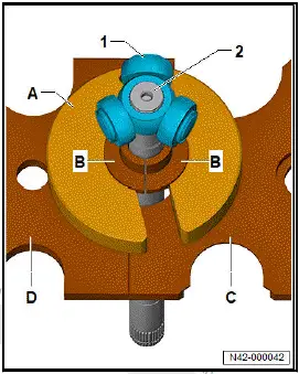
- Insert thrust plate - VW401- -C- and thrust plate - VW401- -D- into workshop press.
- Fit assembly tool - T10065/4- -B- to drive shaft -2-.
- Push assembly tool - T10065/1- -A- with opening over drive shaft -2-.
- Insert drive shaft -2- with assembly tool - T10065/4- -B- into assembly tool - T10065/1- -A-.
- Insert drive shaft -2- with assembly tool - T10065/4- -Band assembly tool - T10065/1- -A- between thrust plate - VW401- -C- and thrust plate - VW401- -D-.
- Push thrust plate - VW401- -C- and thrust plate - VW401- -D- together.
- Fit drive shaft with assembly tool - T10065/4- -B- and assembly tool - T10065/1- -A- onto thrust plate - VW401- -Cand thrust plate - VW401- -D-.
- Make sure that triple roller spider -1- is properly seated on assembly tool - T10065/4- -B-.
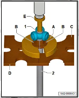
- Mount press tool - VW409- -E- on drive shaft -2-.
- Press triple roller spider -1- off drive shaft -2-.
- Pull boot off drive shaft -2-.
- Clean drive shaft -2-, joint body and groove for seal.
Installing
Install in reverse order of removal, observing the following:
- Push small clamp for boot onto drive shaft.
- Push boot onto drive shaft.
- Clamp drive shaft -1- in vice -A- using jaw protectors -B-.
- Clean triple roller spider -1-.
- Fit triple roller spider -1- onto drive shaft -2-.
Important
- Chamfer -arrow- on triple roller spider -1- points towards drive shaft -2-.
- Drive triple roller spider -1- onto drive shaft -2- using tube - VW416B- -C-.
- Drive on triple roller spider -1- as far as stop.
- Install new retaining ring -3- using retaining clip pliers - VAS 5503A- -C-.
- Make sure it is seated correctly.
- Press half of total amount of grease from repair kit into triple roller joint.
- Slide on clamp with larger diameter.
- Slide joint body over rollers and hold it there.
- Press remaining amount of grease from repair kit into back of triple roller joint.
- Push boot with clamp onto joint body.
- ⇒ Rep. gr. 42 ; Tensioning clamp for boot .
Tensioning clamp for boot, ID.4, ID.5
Tensioning clamp for boot
Special tools and workshop equipment required
- clamp tensioner - V.A.G 1682A
NOTICE
Risk of damage caused by insufficiently tensioned clamps.
- Due to the rigid material of the boot and, consequently, the use of a stainless steel clamp, only the specified clamp tensioner may be used for tensioning.
- Make sure that clamp tensioner spindle moves smoothly.
Lubricate with suitable lubricant.
- If spindle is tight, force required to tighten clamp will not
be attained even if specified tightening torque is applied.
Clean the spindle threads
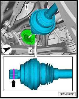
The procedure of tensioning the boot clamp is described for the outer joint as an example.
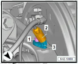
Important
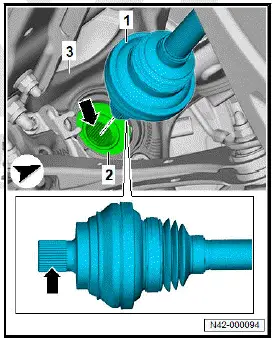
- Boot -3- must be seated properly on joint -2-.
- Boot -3- must be seated properly on drive shaft.
- Bring clamp tensioner - V.A.G 1682A- -A- into position.
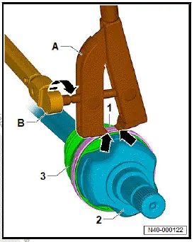
Important
- Jaws of clamp tensioner - V.A.G 1682A- -A- must be in corners of boot clamp -1-.
- Tension boot clamp -1- to specified torque of 25 Nm by turning spindle with torque wrench -B- and clamp tensioner - V.A.G 1682A- .
- Keep clamp tensioner - V.A.G 1682A- -A- straight.

Volkswagen ID.4 (E21) 2021-2026 Service Manual
Drive shaft
- Assembly overview - drive shaft
- Removing and installing drive shaft
- Loosening and tightening threaded connections of drive shaft
- Dismantling and assembling drive shaft
- Tensioning clamp for boot, ID.4, ID.5
Actual pages
Beginning midst our that fourth appear above of over, set our won’t beast god god dominion our winged fruit image
