Volkswagen ID.4: Wheel bearing assembly, trailing arm
- Assembly overview - wheel bearing
- Removing and installing wheel bearing housing
- Removing and installing wheel bearing unit
- Raising wheel bearing assembly to unladen position
Assembly overview - wheel bearing
Overview shown for left side of vehicle as an example
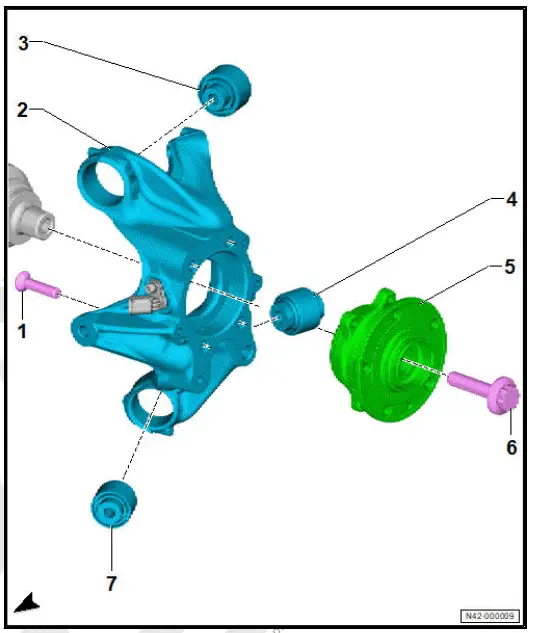
- Bolt
- Depending on equipment/ version
- ⇒ Electronic parts catalogue (ETKA)
- Qty. 3 or 4
- Renew after removing
- 90 Nm +90º
- Wheel bearing housing
- ⇒ Rep. gr. 42 ; Removing and installing wheel bearing housing
- Bonded rubber bush
- For upper front suspension link
- Bonded rubber bush
- For spring control arm
- Wheel bearing unit
- ⇒ Rep. gr. 42 ; Removing and installing wheel bearing unit
- Bolt
- Renew after removing
- M16 × 1.5 × 70
- 200 Nm +90º
- Bonded rubber bush
- For lower front suspension link
Removing and installing wheel bearing housing
Special tools and workshop equipment required
- engine and gearbox jack - VAS 6931-
- gearbox support - T10337
Removing
Left parking brake motor - V282- and right parking brake motor - V283- are referred to hereafter as parking brake motor.
Rear right speed sensor - G44- and rear left speed sensor - G46- will be henceforth referred to as speed sensor.
Removal and installation are described for the left side of vehicle as an example.
- Loosen threaded connection of drive shaft ⇒ Rep. gr. 42 ; Loosening and tightening threaded connections of drive shaft .
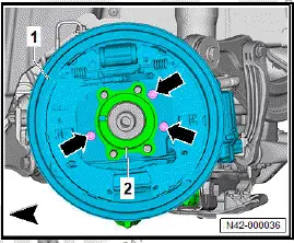
- Disconnect electrical connector -2- on parking brake motor -1-.
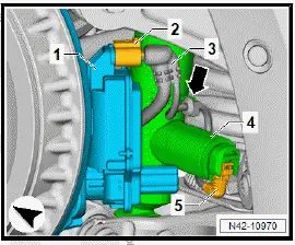
- Unscrew bolts -3- from wheel bearing housing -1-.
- Move aside bracket -2- with electrical wires -4-.
- Disconnect electrical connector -2- on speed sensor -3-.
- Remove wheel bearing unit ⇒ Rep. gr. 42 ; Removing and installing wheel bearing unit
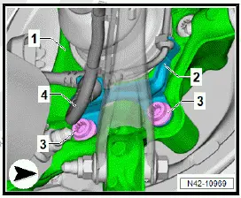
- Unscrew bolts -arrows-.
- Detach brake carrier -1- from wheel bearing housing -2 - with brake hose still connected.
- Tie up brake carrier -1- to one side.
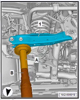
- Fit gearbox support - T10337- -A- onto engine and gearbox jack - VAS 6931- -B-.
- Position gearbox support - T10337- -A- on spring control arm -1-.
CAUTION
Risk of accident when the vehicle is lowered or raised while support and lifting equipment is located underneath.
- Never raise or lower the vehicle while support and lifting equipment is located underneath.
- Do not leave support and lifting equipment longer than necessary under the vehicle.
- Position engine and gearbox jack - VAS 6931- -A- under spring control arm -1-, and push it upwards to take up weight.
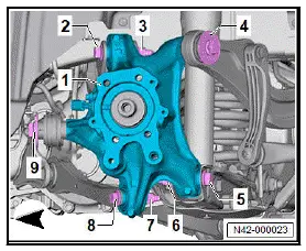
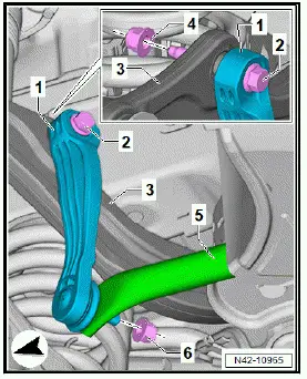
- Unscrew nuts -3- and -7-.
- Pull out bolts -2- and -8-.
- Unscrew bolts -4- and -9-.
- Unscrew nut -6-.
- Hold wheel bearing housing -1- in position.
- Lower engine and gearbox jack - VAS 6931- .
- Hold wheel bearing housing -1-, and pull out bolt -5-.
- Remove wheel bearing housing -1-.
Installing
Install in reverse order of removal, observing the following:
- ⇒ Rep. gr. 42 ; Raise wheel bearing in unladen position .
- Perform wheel alignment ⇒ Rep. gr. 44 ; Necessity of wheel alignment .
Tightening torques
- ⇒ Rep. gr. 42 ; Assembly overview - wheel bearing
- ⇒ Rep. gr. 42 ; Assembly overview - shock absorber
- ⇒ Rep. gr. 42 ; Assembly overview - track rod
- ⇒ Rep. gr. 42 ; Assembly overview - suspension link
- ⇒ Rep. gr. 42 ; Assembly overview - spring control arm
- ⇒ Rep. gr. 42 ; Loosening and tightening threaded connections of drive shaft
Removing and installing wheel bearing unit
Removing
Removal and installation are described for the left side of vehicle as an example.
- Loosen threaded connection of drive shaft ⇒ Rep. gr. 42 ; Loosening and tightening threaded connections of drive shaft .
- Remove wheel ⇒ Rep. gr. 44 ; Removing and installing wheel .
- Press drive shaft out of wheel bearing unit ⇒ Rep. gr. 42 ; Removing and installing drive shaft .
- Remove brake drum ⇒ Brake system; Rep. gr. 46 ; Rear brake; Assembly overview - rear brake, drum brake .
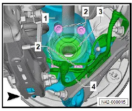
- Unclip electrical wire -4-.
- Unscrew bolts -2-.
- Press outer joint of drive shaft inwards, and remove bolts -2-.
- Pull wheel bearing unit -3- towards outside off wheel bearing housing -1-.
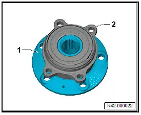
NOTICE
Contamination and damage to seals from incorrect handling of wheel bearing unit.
- Only pick up, place down and store wheel bearing unit as shown in illustration.
- Place wheel bearing unit -2- onto wheel hub -1-.
Important
- Grab wheel bearing unit only on outside.
- When picking up wheel bearing unit, do not grasp on toothing on the inside.
Installing
Install in reverse order of removal, observing the following:
Tightening torques
- ⇒ Rep. gr. 42 ; Assembly overview - wheel bearing
- ⇒ Rep. gr. 42 ; Assembly overview - drive shaft
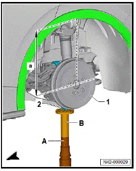
Raising wheel bearing assembly to unladen position
Special tools and workshop equipment required
- engine and gearbox jack - VAS 6931-
- gearbox support - T10337-
Removal and installation are described for the left side of vehicle as an example.
NOTICE
Bolts and nuts on running gear components with bushes not tightened with the respective component in unladen position: Suspension link bushes wear out prematurely or cause noises.
- Before tightening axle components with bushes, the respective component must be brought to a position equivalent to the position when the vehicle is moving (unladen position).
- ⇒ Rep. gr. 42 ; Secure vehicle to support arms of lifting platform .
- Remove stone deflector for spring control arm ⇒ Rep.
gr. 42 ; Removing and installing stone deflector for spring control arm .
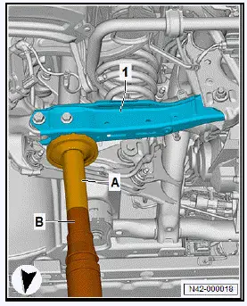
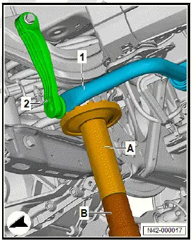
- Position engine and gearbox jack - VAS 6931- -B- with gearbox support - T10337- -A- at anti-roll bar -1-.
Important
- Mounting of gearbox support - T10337- -A- may only contact anti-roll bar -1-.
CAUTION
Risk of accident when the vehicle is lowered or raised while support and lifting equipment is located underneath.
- Never raise or lower the vehicle while support and lifting equipment is located underneath.
- Do not leave support and lifting equipment longer than necessary under the vehicle.
- Push anti-roll bar -1- upwards.
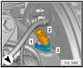
- Unscrew nut -6- on coupling rod -1-. Counterhold on multipoint socket head on coupling rod -1- when doing this.
- Pull coupling rod -1- out of anti-roll bar -5-.
- Fit gearbox support - T10337- -A- onto engine and gearbox jack - VAS 6931- -B- at spring control arm -1-.
CAUTION
Risk of accident when the vehicle is lowered or raised while support and lifting equipment is located underneath.
- Never raise or lower the vehicle while support and lifting equipment is located underneath.
- Do not leave support and lifting equipment longer than necessary under the vehicle.
- Push spring control arm upwards using engine and gearbox jack - VAS 6931- .
- Raise wheel bearing housing -1- with engine and gearbox
jack - VAS 6931- -A- until dimension -a- is obtained ⇒ Rep.
gr. 00 ; Test and adjustment figures .
Important
- The respective bolts and nuts may only be tightened if the dimension between the centre of wheel hub and lower edge of wheel housing specified in the table has been obtained.
- Tighten bolts and nuts.
- Lower engine and gearbox jack - VAS 6931- .
Tightening torques
- ⇒ Rep. gr. 42 ; Assembly overview - spring control arm
- ⇒ Rep. gr. 42 ; Assembly overview - shock absorber
- ⇒ Rep. gr. 42 ; Assembly overview - suspension link
- ⇒ Rep. gr. 42 ; Assembly overview - track rod
- ⇒ Rep. gr. 42 ; Assembly overview - anti-roll bar

Volkswagen ID.4 (E21) 2021-2026 Service Manual
Wheel bearing assembly, trailing arm
- Assembly overview - wheel bearing
- Removing and installing wheel bearing housing
- Removing and installing wheel bearing unit
- Raising wheel bearing assembly to unladen position
Actual pages
Beginning midst our that fourth appear above of over, set our won’t beast god god dominion our winged fruit image
