Volkswagen ID.4: Suspension strut, shock absorber, spring
- Exploded view - shock absorber
- Assembly overview - spring
- Removing and installing shock absorber
- Renewing shock absorber
- Removing and installing spring
- Renewing spring
Exploded view - shock absorber
The exploded view here applies to the left side of the vehicle.
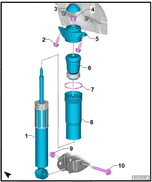
- Shock absorber
- ⇒ Rep. gr. 42 ; Removing and installing shock absorber
- Bolt
- 2x
- Renew after removing
- M 10 x 35
- 50 Nm +90º
- Cover
- Nut
- Renew after removing
- M10
- 25 Nm
- Shock absorber mounting
- Bump stop
- Cable tie
- Renew after removing
- Protective tube
- Nut
- Renew after removing
- M 12 x 1.5
- 70 Nm +180º
- Bolt
- Renew after removing
- M 12 x 1.5 x 90
Assembly overview - spring
The overview is shown for the left side of vehicle as an example.
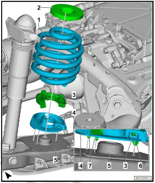
- Shock absorber
- ⇒ Rep. gr. 42 ; Removing and installing shock absorber
- Bolt
- 2x
- Renew after removing
- M 10 x 35
- 50 Nm +90º
- Cover
- Nut
- Renew after removing
- M10
- 25 Nm
- Shock absorber mounting
- Bump stop
- Cable tie
- Renew after removing
- Protective tube
- Nut
- Renew after removing
- M 12 x 1.5
- 70 Nm +180º
- Bolt
- Renew after removing
- M 12 x 1.5 x 90
Removing and installing shock absorber
The overview is shown for the left side of vehicle as an example.
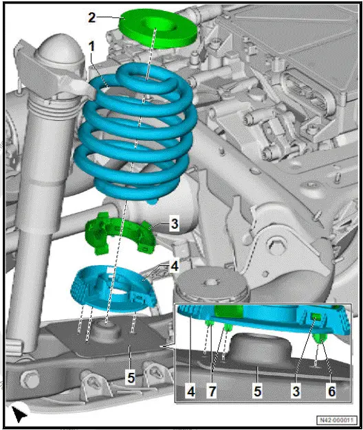
- Spring
- Depending on equipment/ version
- Allocation ⇒ Electronic parts catalogue (ETKA)
- ⇒ Rep. gr. 42 ; Removing and installing spring
- Spring seat
- Support
- Spring seat
- Spring control arm
- ⇒ Rep. gr. 42 ; Assembly overview - spring control arm
- ⇒ Rep. gr. 42 ; Removing and installing spring control arm
- Retaining clip
- Guides
Removing and installing shock absorber
Special tools and workshop equipment required
- engine and gearbox jack - VAS 6931-
Removing
Removal and installation are described for the left side of vehicle as an example.
- Remove wheel ⇒ Rep. gr. 44 ; Removing and installing wheel .
- ⇒ Rep. gr. 42 ; Secure vehicle to support arms of lifting platform .
- Unbolt rear left vehicle level sender - G76- from spring control arm ⇒ Rep. gr. 43 ; Removing and installing rear vehicle level sender [G76]/[G77] .
Vehicles with adaptive chassis control
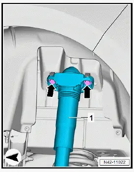
- Disconnect electrical connector -3- on rear left shock absorber damping adjustment valve - N338- .
- Pull electrical wire -arrow- off retainer on shock absorber -2-.
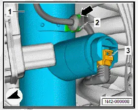
All vehicles (continued)
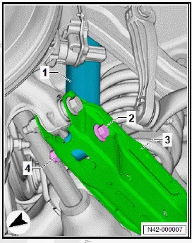
- Position engine and gearbox jack - VAS 6931- under spring control arm, and push upwards.
- Unscrew bolts -arrows- for shock absorber -1-.
- Unscrew nut -4-.
- Pull out bolt -2-.
- Press together shock absorber -1-.
- Guide shock absorber -1- out of spring control arm -3-.
Installing
Install in reverse order of removal, observing the following:
Important
- The shock absorber must be bolted to the spring control arm only in unladen position ⇒ Rep. gr. 42 ; Raising wheel bearing assembly to unladen position .
- Carry out required function/functions using ⇒ Vehicle diagnostic tester ⇒ Rep. gr. 00 ; Access to diagnoses .
Tightening torques
- ⇒ Rep. gr. 42 ; Assembly overview - shock absorber
- ⇒ Rep. gr. 43 ; Assembly overview - rear vehicle level senders
Renewing shock absorber
Special tools and workshop equipment required
- Extension - T10001/14-
- Extension - T10001/3-
- Ratchet - T10001/11-
- Suspension strut support clamp - V.A.G 1752/20-
- Torque wrench - V.A.G 1331-
- shock absorber set - T10001-
- suspension strut support clamp - V.A.G 1752/20-
Remove shock absorber ⇒ Rep. gr. 42 ; Removing and installing shock absorber .
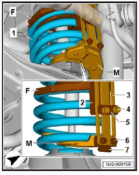
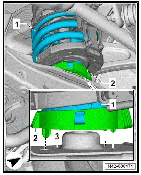
Dismantling shock absorber
- Clamp suspension strut support clamp - V.A.G 1752/20- in a vice.
- Clamp shock absorber into suspension strut support clamp - V.A.G 1752/20- .
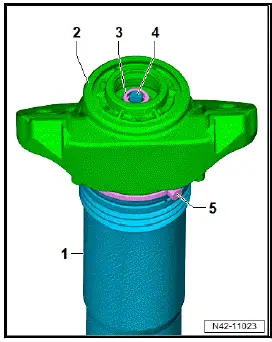
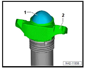
- Lever cover -1- off shock absorber mounting -2-.
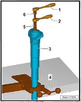
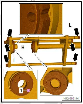
- Fit tools from shock absorber set - T10001- as shown in illustration, and loosen threaded connection for shock absorber mounting.
- Commercially available ratchet
- Ratchet - T10001/11-
- Shock absorbers
- Suspension strut support clamp - V.A.G 1752/20-
- Extension - T10001/3-
- Extension - T10001/14-
- Open cable tie -5-.
- Unscrew nut -3-.
- Pull shock absorber mounting -2- off shock absorber -1-.
- Remove protective tube -1- from shock absorber mounting -2-.
- Remove protective tube -1-.
Assembling shock absorber
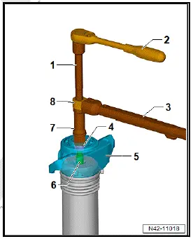
- Fit tools from shock absorber set - T10001- as shown in illustration, and tighten threaded connection. When doing this, counterhold using ratchet.
- Tool insert - T10001/14-
- Commercially available ratchet
- Torque wrench - V.A.G 1331-
- Nut
- Shock absorber mounting
- Piston rod
- Extension - T10001/3-
- Ring spanner insert AF 21, commercially available
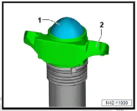
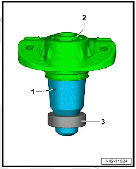
- Insert stop buffer -1- to stop into shock absorber mounting -2-.
- Make sure that seal -3- is firmly seated.
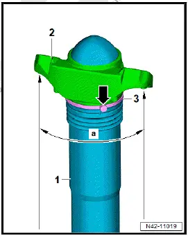
- Push protective tube -1- to stop onto shock absorber mounting -2-.
- Fit and secure cable tie -3-.
Important
- The fastener -arrow- of the cable tie -3- must be located within area -a-.
- Closure -arrow- of cable tie must point outwards when shock absorber is installed.
- Install cover -1- to shock absorber mounting -2-, and ensure that it is seated firmly.
Tightening torques
- ⇒ Rep. gr. 42 ; Assembly overview - shock absorber
Removing and installing spring
Special tools and workshop equipment required
- Spreader device - VAS 6274/8-
- Supplement set - VAS 6274/12-
- Supplement set - VAS 6274/15A-
- Thrust plates - VAS 6274/16-
- spring compressing system - VAS 6274-
Removal and installation are described for the left side of vehicle as an example.
Removing
- Remove wheel ⇒ Rep. gr. 44 ; Removing and installing wheel .
- ⇒ Rep. gr. 42 ; Secure vehicle to support arms of lifting platform .
- Remove stone deflector for spring control arm ⇒ Rep.
gr. 42 ; Removing and installing stone deflector for spring control arm .
- Remove rear centre underbody cladding ⇒ General body repairs, exterior; Rep. gr. 66 ; Underbody cladding; Removing and installing rear centre underbody cladding .
- Remove rear underbody cladding ⇒ General body repairs, exterior; Rep. gr. 66 ; Underbody cladding; Removing and installing rear underbody cladding .
Vehicles with rear left vehicle level sender - G76-
- Unbolt rear left vehicle level sender - G76- from spring control arm ⇒ Rep. gr. 43 ; Removing and installing rear vehicle level sender [G76]/[G77] .
All vehicles (continued)
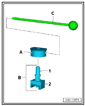
Preparing spreader device for rear suspension link:
- Screw threaded spindle -1- from spreader device - VAS 6274/8- into plastic-padded plate -2- from spreader device - VAS 6274/8- .
- Screw support plate - VAS 6274/15-8- -A- onto threaded spindle -1-.
- Screw in gripping rod included with spreader device - VAS 6274/8- -C-.
Important
- Please pay attention to the relevant side of the vehicle.
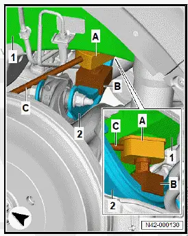
All vehicles (continued)
- Position support plate -A- on longitudinal member -1-.
- Fit support plate -B- onto suspension link at upper front -2-.
- Align tools between upper front suspension link -2- and longitudinal member -1- via gripping rod -1-.
- Turn threaded spindle until both support plates make contact.
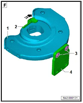
- Push slide lock -2- in direction of -arrow-.
- Secure locating element -4- to thrust plate with slide lock - VAS 6274/16-2- -1- using bolts -3-.
Important
- Tighten bolts -3- to 10 Nm.
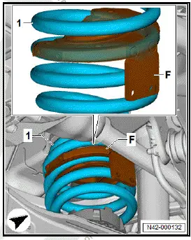
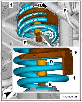
- Insert thrust plate with slide lock - VAS 6274/16-2- -F- into spring -1- at bottom.
Important
- Plastic support must face downwards.
- Turn thrust plate with slide lock -F- upwards at spring -1-.
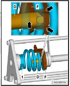
- Insert 69 mm piston - VAS 6274/12-6- -D- into thrust plate with slide lock -F-.
Important
- Markings on piston -D- and thrust plate with slide lock -Fmust be offset relative to one another by 90º.
- Push piston -D- through thrust plate with slide lock -F-.
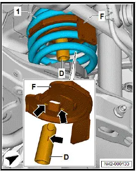
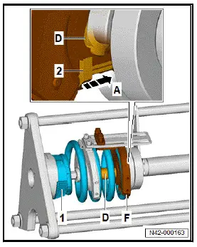
- Turn piston -D- by 90º.
- Pull piston -D- downwards into guides on thrust plate with slide lock -F-.
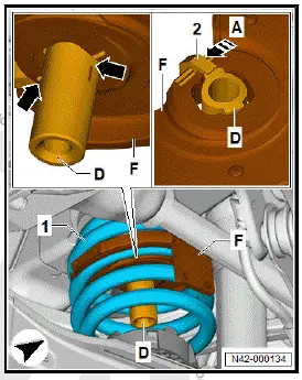
Important
- Markings -arrows- must align properly.
- Push slide lock -2- to stop in direction of -arrow A-. This will fix piston -D- in position.
- Turn thrust plate with slide lock -F- as far as possible upwards on spring coils -1-.
- Make sure when doing this that plastic support rests against spring coils -1-.
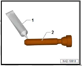
NOTICE
Risk of damage to spindle due to lacking or wrong grease.
- Apply a thin coat of molybdenum disulfide to the front area of the spindle.
- Apply a thin coat of molybdenum disulfide -1- to the front area of the spindle -2-. For allocation, refer to ⇒ Operating manual of spring compressing system - VAS 6274- .
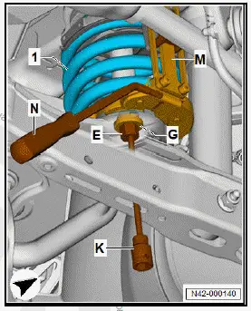
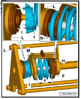
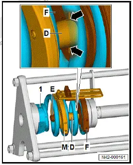
- Guide spindle - VAS 6274/15-1A- -E- into spring -1-, and screw into piston -D-.
- Insert thrust plate with swivel mounting - VAS 6274/16-1- -M- into spring -1-.
Important
- Plastic support must face upwards.
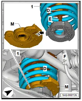
- Turn thrust plate with swivel mounting -M- upwards at spring -1-.
- Guide hexagon of spindle -E- through hole in thrust plate with swivel mounting -M-.
- Guide spindle -E- with socket with ball head (AF8) - VAS 6274/15-3- .
- Unscrew spindle -E- as far as possible.
Important
- Shank - without spindle threads - -E- must be located below thrust plate with swivel mounting -M-.
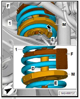
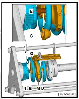
- Position spindle attachment - VAS 6274/15-2A- -G- on spindle -E-.
- Turn thrust plate with swivel mounting -M- as far as possible downwards at spring -1-.
- Turn thrust plate with swivel mounting -M- upwards at spring coil -1-.
- Align spindle attachment -G- in thrust plate with swivel mounting -M-.
Important
- Make sure that spindle attachment -G- makes proper contact with guide of thrust plate with swivel mounting -M-.
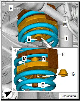
- Align thrust plate with slide lock -F- and thrust plate with swivel mounting -M-.
Important
- Arrow on thrust plate with swivel mounting -M- must face in direction of travel.
Important
- Make sure that spring is properly seated in thrust plates.
- Secure locating element -3- with bracket -7- to thrust plate with swivel mounting -M- -5-.
Important
- Tighten bolts -6- to 10 Nm.
- Connect thrust plate with swivel mounting -M- and thrust plate with slide lock -F- via brackets -5- and bolts -4-.
Important
- Tighten bolts -4- to 10 Nm.
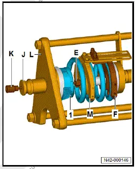
- Position socket with ball head (AF8) - VAS 6274/15-3- -K- at spindle -E-.
Important
- Make sure that spindle attachment -G- is correctly seated in swivel mounting of thrust plate -M-.
- Make sure that spring -1- is properly seated in thrust plate with swivel mounting -M-.
- Tighten spindle -E- by hand.
- Insert counter-hold tool - VAS 6274/7- -N- into thrust plate with swivel mounting -M-.
- Tension spring -1- using socket wrench -K- while counterholding with counter-hold tool -N-.
- Compress spring -1- until support -2- can be removed.
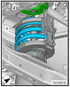
- Carefully lever spring -1- with spring seat -2- off spring control arm -3-.
- Remove spring -1- with tools.
Installing
Install in reverse order of removal, observing the following:
- Insert lug of spring seat -2- into hole in spring control arm -3-.
Renewing spring
Special tools and workshop equipment required
- Spreader device - VAS 6274/8-
- Supplement set - VAS 6274/12-
- Supplement set - VAS 6274/15A-
- Thrust plates - VAS 6274/16-
- foot pump - VAS 6179-
- hydraulic tensioning device - VAS 6274/9-
Removing
- Remove spring ⇒ Rep. gr. 42 ; Removing and installing spring .
- Connect foot pump - VAS 6179- to hydraulic tensioning device - VAS 6274/9- .
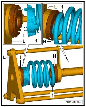
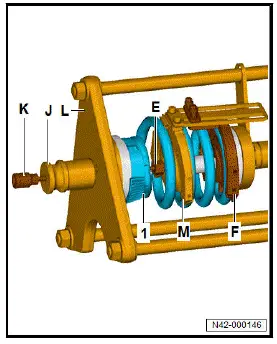
- Check nuts -arrows- on hydraulic tensioning device - VAS 6274/9- -L- for secure fit.
- Attach centring disc of spring mounting - VAS 6274/15-6A- -I- to tensioning device -L-.
Important
- Make sure that recess of centring disc -I- faces towards vehicle side L or R, respectively, and that locating element is fitted at top.
- Secure centring disc -9- with bolt -1-.
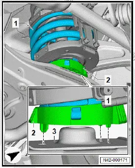
- Place adapter plate with magnets - VAS 6274/15-5- -H- onto flexible mounting, making sure that magnetic holder is correctly seated.
- Insert spring -1- with tools into tensioning device -L-.
Important
- Make sure that guides on mounting -1- are located in holes of centring disc -I-.
- Hold spring in this position.
- Connect foot pump -L- to tensioning device.
- Withdraw piston of tensioning device -L- until spring -1- is securely fitted.
Important
- Do not tension spring -1-.
- Spring -1- must be seated correctly at guide of adapter plate -H-.
- Determine and make note of dimension -a-.
- Mark installation position of thrust plate with slide lock - VAS 6274/16-2- -F- and thrust plate with swivel mounting - VAS 6274/16-1- -M- on spring -1-.
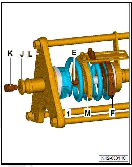
- Fit centring sleeve - VAS 6274/15-7- -J- in position.
- Position socket with ball head (AF8) - VAS 6274/15-3- -K- on spindle 130 mm (AF19) - VAS 6274/15-1A- -E-.
- Relieve tension from spring -1- via socket -K- at tensioning device -L-.
- Move back piston of tensioning device -L- using foot pump.
- Make sure that spring -1- is properly seated in tensioning device -L-.
- Relieve tension from spring -1- via socket -K- in tensioning device -L-.
- Move piston of tensioning device -L- further back via foot pump.
- Detach tools.
Installing
Install in reverse order of removal, observing the following:
- Insert spring -1- into tensioning device -L-.
Important
- Markings must be transferred to new coil spring.
- Make sure that guides on mounting -1- are located in holes of centring disc -I-.
- Hold spring in this position.
- Connect foot pump -L- to tensioning device.
- Withdraw piston of tensioning device -L- as far as spring -1-.
Important
- Spring -1- must NOT be tensioned.
- Make sure that spring -1- is properly seated on guide of adapter plate -M-.
- Retract piston of tensioning device -L- until spring -1- is securely fitted.
- Insert thrust plate -F- in installation position.
- Move 69 mm piston - VAS 6274/12-6- -D- through thrust plate -F-.
- Insert piston -D- into thrust plate -F-.
Important
- Markings -arrow- on piston -D- and thrust plate -F- must be offset 90ºrelative to one another.
- Turn piston -D- by 90º.
- Pull piston -D- downwards into guides on thrust plate -F-.
Important
- Markings -arrows- must align properly.
- Insert thrust plate -M- observing markings for orientation.
- Screw spindle -E- into piston -D- using socket with ball head (AF8) - VAS 6274/15-3- .
- Attach locating element.
Important
- Tighten bolts to 10 Nm.
- Push slide lock -2- to stop in direction of -arrow A-. This will fix piston -D- in position.
- Push spindle attachment - VAS 6274/15-2A- -G- onto spindle -E-.
- Screw spindle -E- further into piston -D-.
- Screw in spindle -E- until spindle attachment -G- rests against thrust plate -M-.
- Make sure that spindle attachment -G- is correctly seated in hole of thrust plate -M-.
- Fit centring sleeve - VAS 6274/15-7- -J- in position.
- Bring socket -K- in position on spindle -E-.
Important
- Spring -1- must be properly seated in tensioning device -L-.
- Turn socket -K- 2 turns.
- Turn socket -K- far enough to make sure that spring -1- cannot slip out of tensioning device -L-.
Important
- Spring -1- and tools must be seated correctly.
- Operate foot pump, and slightly tighten spring -1- via piston of tensioning device -L-.
- Tension spring -1- via spindle -E-. Keep retracting piston of tensioning device -L- over and over again.
- Tension spring -1- until dimension a determined beforehand is obtained.
- Move back piston of tensioning device -L- via foot pump.
- Hold spring -1- in place.
- Remove spring -1- with tools from tensioning device -L-.
- Install spring ⇒ Rep. gr. 42 ; Removing and installing spring .

Volkswagen ID.4 (E21) 2021-2026 Service Manual
Suspension strut, shock absorber, spring
- Exploded view - shock absorber
- Assembly overview - spring
- Removing and installing shock absorber
- Renewing shock absorber
- Removing and installing spring
- Renewing spring
Actual pages
Beginning midst our that fourth appear above of over, set our won’t beast god god dominion our winged fruit image
