Volkswagen ID.4: Suspension link, track rod
- Assembly overview - suspension link
- Assembly overview - track rod
- Assembly overview - spring control arm
- Removing and installing track rod
- Removing and installing spring control arm
- Removing and installing lower suspension link
- Removing and installing upper rear suspension link
- Removing and installing upper front suspension link
Assembly overview - suspension link
Assembly overview - upper suspension link
The overview is shown for the left side of the vehicle as an example.
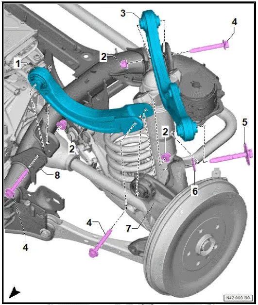
- Upper link (front)
- ⇒ Rep. gr. 42 ; Removing and installing upper front suspension link
- Nut
- M12 × 1.5
- Qty. 3
- Renew after removing
- Rear upper suspension link
- ⇒ Rep. gr. 42 ; Removing and installing upper rear suspension link
- Bolt
- M 12 × 1.5 × 90
- Qty. 3
- Renew after removing
- 70 Nm +180º
- Bolt
- M14 × 1.5 × 100
- Renew after removing
- 130 Nm +180º
- Washer
- Wheel bearing housing
- ⇒ Rep. gr. 42 ; Assembly overview - wheel bearing
- ⇒ Rep. gr. 42 ; Removing and installing wheel bearing housing
- Subframe
- ⇒ Rep. gr. 42 ; Assembly overview - subframe
- ⇒ Rep. gr. 42 ; Fixing subframe in position
- ⇒ Rep. gr. 42 ; Taking up weight of subframe using scissor-type assembly platform
- ⇒ Rep. gr. 42 ; Removing and installing rear axle
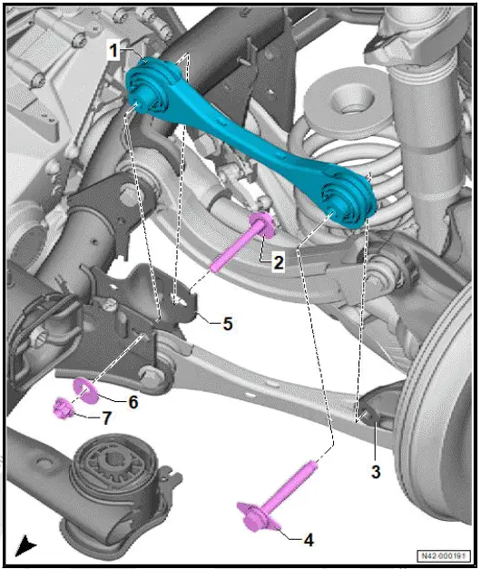
Assembly overview - lower suspension link
The overview is shown for the left side of the vehicle as an example.
- Subframe
- ⇒ Rep. gr. 42 ; Assembly overview - subframe
- ⇒ Rep. gr. 42 ; Fixing subframe in position
- ⇒ Rep. gr. 42 ; Taking up weight of subframe using scissor-type assembly platform
- ⇒ Rep. gr. 42 ; Removing and installing rear axle
- Bolt
- Renew after removing
- M 12 × 1.5 × 80
- 70 Nm +180º
- Lower suspension link
- ⇒ Rep. gr. 42 ; Removing and installing lower suspension link
- Bolt
- Renew after removing
- M 12 × 1.5 × 80
- 70 Nm +180º
- Wheel bearing housing
- ⇒ Rep. gr. 42 ; Assembly overview - wheel bearing
- ⇒ Rep. gr. 42 ; Removing and installing wheel bearing housing
- Nut
- Renew after removing
- M12 × 1.5
- 70 Nm +180º
- Electrical wire
- Nut
- Renew after removing
- M12 × 1.5
- 70 Nm +180º
- Bracket
- Bracket
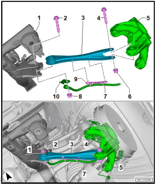
Assembly overview - track rod
Overview shown for left side of vehicle as an example
- Track rod
- Closed side points upwards in situ
- ⇒ Rep. gr. 42 ; Overview of fitting locations - rear axle
- ⇒ Rep. gr. 42 ; Removing and installing track rod
- Eccentric bolt
- M 12 x 1.5
- Wheel bearing housing
- ⇒ Rep. gr. 42 ; Assembly overview - wheel bearing
- ⇒ Rep. gr. 42 ; Removing and installing wheel bearing housing
- Bolt
- Renew after removing
- M14 × 1.5 × 100
- 130 Nm +180º
- Subframe
- ⇒ Rep. gr. 42 ; Assembly overview - subframe
- ⇒ Rep. gr. 42 ; Fixing subframe in position
- ⇒ Rep. gr. 42 ; Taking up weight of subframe using scissor-type assembly platform
- ⇒ Rep. gr. 42 ; Removing and installing rear axle
- Eccentric washer
- Nut
- M 12 x 1.5 x 97.5
- 95 Nm
Assembly overview - spring control arm
Overview shown for left side of vehicle as an example
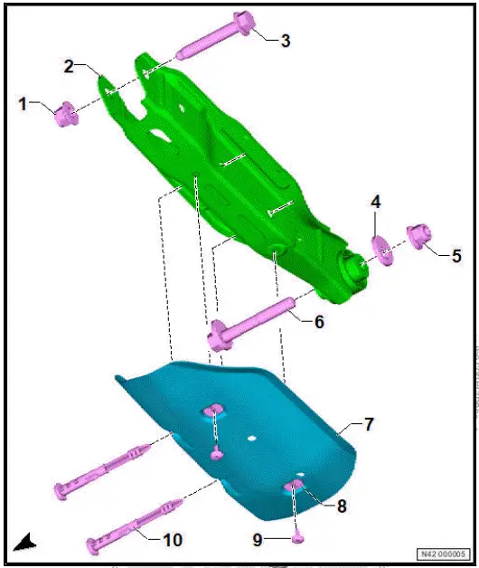
- Nut
- Renew after removing
- M14 × 1.5
- Spring control arm
- ⇒ Rep. gr. 42 ; Removing and installing spring control arm
- Bolt
- Renew after removing
- M14 × 1.5 × 90
- 130 Nm +180º
- Eccentric washer
- Nut
- Renew after removing
- M14 × 1.5
- 190 Nm
- Eccentric bolt
- M14 × 1.5 × 95
- Stone deflector for spring control arm
- ⇒ Rep. gr. 42 ; Removing and installing stone deflector for spring control arm
- Spreader rivet
- Qty. 2
- Bolt
- Qty. 2
- 2 Nm
- Retaining clip
- Qty. 2
- Renew after removing
Removing and installing track rod
Special tools and workshop equipment required
- engine and gearbox jack - VAS 6931-
- gearbox support - T10337-
Removal and installation are described for the left side of vehicle as an example.
Removing
- Remove wheel ⇒ Rep. gr. 44 ; Removing and installing wheel .
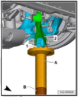
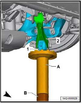
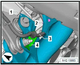
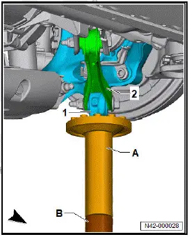
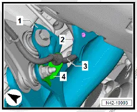
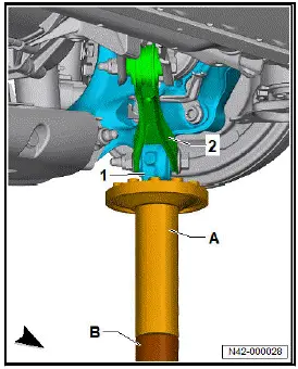
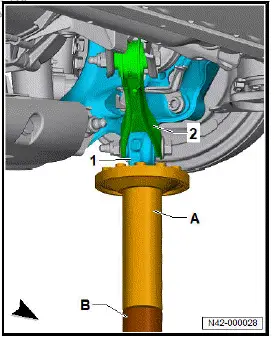
- Position engine and gearbox jack - VAS 6931- -B- with gearbox support - T10337- -A- under wheel bearing housing -1-, and push upwards to provide support.
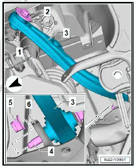
- Unscrew nut -4-.
- Pull bolt -2- out of wheel bearing housing -3-.
- Swing upper front suspension link -1- on wheel bearing housing -3- upwards.
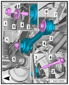
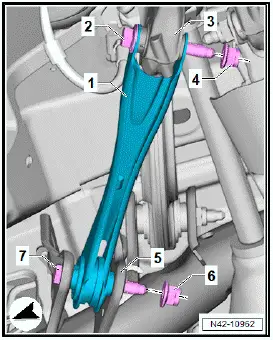
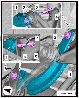
- Mark position of eccentric bolt -4- relative to subframe -2-.
- Unscrew nut -1-, and remove eccentric washer -5-.
- Pull bolt -4- out of subframe -2-.
- Unscrew bolt -6- from wheel bearing housing -7-.
- Take out track rod -3-.
Installing
Install in reverse order of removal, observing the following:
- Tighten threaded connections in unladen position ⇒ Rep.
gr. 42 ; Raising wheel bearing assembly to unladen position .
- Carry out wheel alignment ⇒ Rep. gr. 44 ; Wheel alignment .
Tightening torques
- ⇒ Rep. gr. 42 ; Assembly overview - track rod
- ⇒ Rep. gr. 42 ; Assembly overview - suspension link
Removing and installing stone deflector for spring control arm
Special tools and workshop equipment required
- release tool - T10236-
Removal and installation are described for the left side of vehicle as an example.
Removing
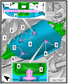
- Unscrew bolts -6-.
- Pull out pins -3- as far as stop using release tool - T10236- .
- Pull retaining clips -4- out of spring control arm -1- using release tool - T10236- .
- Pull stone deflector for spring control arm -2- at spreader rivets -5- off spring control arm -1-, and remove it.
Installing
Install in reverse order of removal, observing the following:
- Pay attention to allocation "L" and "R", and to arrow indicating direction of travel.
Tightening torques
- ⇒ Rep. gr. 42 ; Assembly overview - spring control arm
Removing and installing spring control arm
Special tools and workshop equipment required
- engine and gearbox jack - VAS 6931-
- gearbox support - T10337-
Removing
Rear left vehicle level sender - G76- will henceforth be referred to as "rear left vehicle level sender".
Removal and installation are described for the left side of vehicle as an example.
- Remove wheel ⇒ Rep. gr. 44 ; Removing and installing wheel .
- Remove stone deflector for spring control arm ⇒ Rep.
gr. 42 ; Removing and installing stone deflector for spring control arm .
Vehicles with rear left vehicle level sender
- Unbolt rear left vehicle level sender from spring control arm ⇒ Rep. gr. 43 ; Removing and installing rear vehicle level sender [G76]/[G77] .
All vehicles (continued)
- Remove spring ⇒ Rep. gr. 42 ; Removing and installing spring .
CAUTION
Risk of accident when the vehicle is lowered or raised while support and lifting equipment is located underneath.
- Never raise or lower the vehicle while support and lifting equipment is located underneath.
- Do not leave support and lifting equipment longer than necessary under the vehicle
- Position engine and gearbox jack - VAS 6931- -B- with gearbox support - T10337- -A- under wheel bearing housing -1-, and push upwards to provide support.
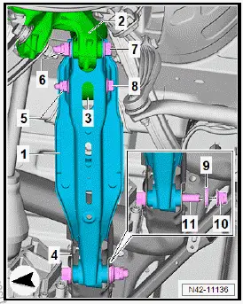
- Mark position of eccentric bolt -11- relative to subframe -4-.
- Unscrew nut -5-, and pull out bolt -8- for shock absorber -3-.
- Unscrew nut -6-, and pull out bolt -7- on wheel bearing housing -2-.
- Unscrew nut -10-, and remove eccentric washer -9-.
- Pull bolt -11- out of subframe -4-.
- Remove spring control arm -1-.
Installing
Install in reverse order of removal, observing the following:
- Align bolt -11- according to marking made beforehand, and tighten nut -10- hand-tight.
- Tighten threaded connections in unladen position ⇒ Rep.
gr. 42 ; Raising wheel bearing assembly to unladen position .
- Carry out wheel alignment ⇒ Rep. gr. 44 ; Wheel alignment .
Vehicles with rear left vehicle level sender
- Carry out required function/functions using ⇒ Vehicle diagnostic tester ⇒ Rep. gr. 00 ; Access to diagnoses .
All vehicles (continued)
Tightening torques
- ⇒ Rep. gr. 42 ; Assembly overview - spring control arm
- ⇒ Rep. gr. 42 ; Assembly overview - shock absorber
Removing and installing lower suspension link
Special tools and workshop equipment required
- engine and gearbox jack - VAS 6931-
- gearbox support - T10337-
Removal and installation are described for the left side of vehicle as an example.
Removing
- Remove wheel ⇒ Rep. gr. 44 ; Removing and installing wheel .
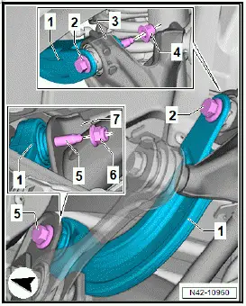
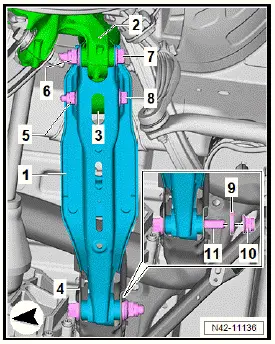
- Unclip retainer -1- for electrical wire -2- from lower suspension link -3-.
- Press together locking lugs of retainer -1- on inside of lower suspension link -3-.
- Pull electrical wire -3- off retainer -4-.
- Position engine and gearbox jack - VAS 6931- -B- with gearbox support - T10337- -A- under wheel bearing housing -1-, and push upwards to provide support.
- Unscrew nut -4- for lower suspension link -1- from wheel bearing housing -3-.
- Unscrew nut -6- for lower suspension link -1- on subframe -5-.
- Remove bracket.
- Pull bolts -2- and -7- out of lower suspension link -1-.
- Remove lower suspension link -1-.
Installing
Install in reverse order of removal, observing the following:
- Make sure that guide groove of bracket -4- is properly seated in subframe -1-.
- Tighten threaded connections in unladen position ⇒ Rep.
gr. 42 ; Raising wheel bearing assembly to unladen position .
- Perform wheel alignment ⇒ Rep. gr. 44 ; Necessity of wheel alignment .
Tightening torques
- ⇒ Rep. gr. 42 ; Assembly overview - suspension link
Removing and installing upper rear suspension link
Special tools and workshop equipment required
- engine and gearbox jack - VAS 6931-
- gearbox support - T10337-
Removal and installation are described for the left side of vehicle as an example.
Removing
- Remove wheel ⇒ Rep. gr. 44 ; Removing and installing wheel .
- Remove rear underbody cladding ⇒ General body repairs, exterior; Rep. gr. 66 ; Underbody cladding; Removing and installing rear underbody cladding .
- Position engine and gearbox jack - VAS 6931- -B- with gearbox support - T10337- -A- under wheel bearing housing -1-, and push upwards to provide support.
- Remove coupling rod ⇒ Rep. gr. 42 ; Removing and installing coupling rod .
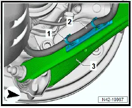
- Unscrew nut -5-.
- Unscrew bolt -2- from wheel bearing housing -1-.
- Pull bolt -4- out of subframe -6-.
- Remove upper rear suspension link -3-.
Installing
Install in reverse order of removal, observing the following:
- Tighten threaded connections in unladen position ⇒ Rep.
gr. 42 ; Raising wheel bearing assembly to unladen position .
- Perform wheel alignment ⇒ Rep. gr. 44 ; Necessity of wheel alignment .
Tightening torques
- ⇒ Rep. gr. 42 ; Assembly overview - suspension link
- ⇒ Rep. gr. 42 ; Assembly overview - anti-roll bar
Removing and installing upper front suspension link
Special tools and workshop equipment required
- engine and gearbox jack - VAS 6931-
- gearbox support - T10337-
Removing
- Remove wheel ⇒ Rep. gr. 44 ; Removing and installing wheel .
- Remove rear centre underbody cladding ⇒ General body repairs, exterior; Rep. gr. 66 ; Underbody cladding; Removing and installing rear centre underbody cladding .
- Position engine and gearbox jack - VAS 6931- -B- with gearbox support - T10337- -A- under wheel bearing housing -1-, and push upwards to provide support
- Unscrew nut -4-.
- Pull bolt -2- out of wheel bearing housing -3-.
- Unscrew nut -6-.
- Pull bolt -5- out of subframe -7-.
- Remove upper front suspension link -1-.
Installing
Install in reverse order of removal, observing the following:
- Tighten threaded connections in unladen position ⇒ Rep.
gr. 42 ; Raising wheel bearing assembly to unladen position .
- Perform wheel alignment ⇒ Rep. gr. 44 ; Necessity of wheel alignment .
Tightening torques
- ⇒ Rep. gr. 42 ; Assembly overview - suspension link

Volkswagen ID.4 (E21) 2021-2026 Service Manual
Suspension link, track rod
- Assembly overview - suspension link
- Assembly overview - track rod
- Assembly overview - spring control arm
- Removing and installing track rod
- Removing and installing spring control arm
- Removing and installing lower suspension link
- Removing and installing upper rear suspension link
- Removing and installing upper front suspension link
Actual pages
Beginning midst our that fourth appear above of over, set our won’t beast god god dominion our winged fruit image
