Volkswagen ID.4: Removing and installing rear motor
Assembly overview - rear motor
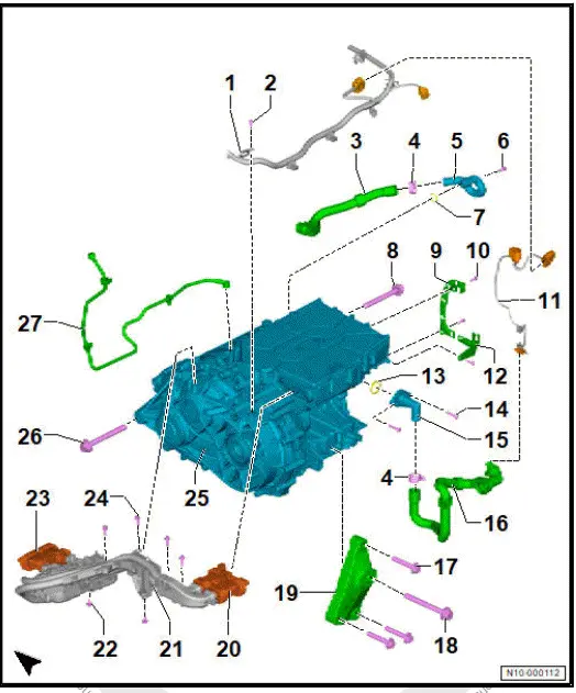
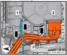
- Potential equalisation line
- Bolt
- 8 Nm
- Coolant hose
- Clamp
- Union
- Bolt
- Renew after removing
- 8 Nm +45º
- O-ring
- Bolt
- Renew after removing
- 130 Nm +180º
- Cable guide
- Bolt
- Qty. 3
- Renew after removing
- 4 Nm +90º
- Electrical wire
- Cable guide
- O-ring
- Bolt
- Qty. 2
- Renew after removing
- 8 Nm +45º
- Union
- Coolant hose
- Bolt
- Qty. 3
- Renew after removing
- 70 Nm +180º
- Bolt
- Renew after removing
- 130 Nm +180º
- Motor support
- Electrical connector
- High voltage
- Cable guide
- Bolt
- Qty. 2
- 8 Nm
- Electrical connector
- High voltage
- Bolt
- Qty. 4
- 8 Nm
- Three-phase current drive - VX54-
- With power and control electronics for electric drive - JX1-
- ⇒ Rep. gr. 10 ; Removing rear motor
- ⇒ Rep. gr. 10 ; Installing rear motor
- Bolt
- Renew after removing
- 130 Nm +180º
- Breather line
Assembly overview - oil temperature sender
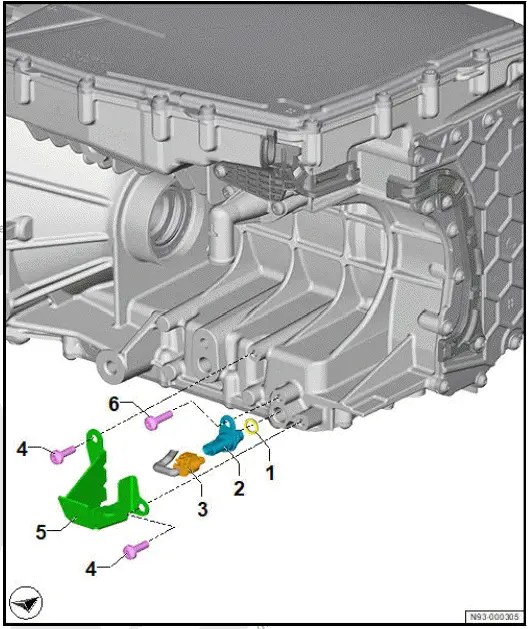
- Seal
- Oil temperature sender - G8-
- ⇒ Rep. gr. 93 ; Removing and installing oil temperature sender -G8-
- Electrical connector
- Bolt
- Qty. 2
- Renew after removing
- 8 Nm +45º
- Guard plate
- Bolt
- Renew after removing
- 8 Nm +45º
Removing rear motor
Special tools and workshop equipment required
- Pin - 3282/29-
- Pin - 3282/34-
- Pin - 3282/50-
- bit XZN 16 - T10198-
- engine and gearbox jack - VAS 6931-
- engine bung set - VAS 6122-
- gearbox support - 3282-
- lifting tackle - VAS 501 019-
- workshop hoist - VAS 6100-
Three-phase current drive - VX54- with power and control electronics for electric drive - JX1- is referred to hereafter as "motor".
Removing
DANGER
High voltage can cause fatal injury.
Danger of severe or fatal injuries from electric shock or electric arcs.
- Have a high-voltage technician (HVT) or a high-voltage expert (HVE) de-energise the high-voltage system.
- ⇒ Rep. gr. 93 ; De-energise high-voltage system .
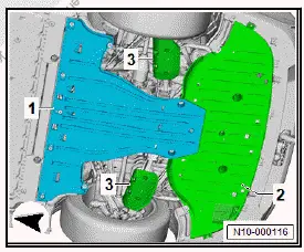
- Remove rear centre underbody cladding -1- ⇒ General body repairs, exterior; Rep. gr. 66 ; Underbody cladding; Removing and installing rear centre underbody cladding .
- Remove rear underbody cladding -2- ⇒ General body repairs, exterior; Rep. gr. 66 ; Underbody cladding; Removing and installing rear underbody cladding .
- Remove stone deflector for spring control arm -3- ⇒ Running gear, axles, steering; Rep. gr. 42 ; Suspension link, track rod; Removing and installing stone deflector for spring control arm .
- Remove left and right drive shaft ⇒ Running gear, axles, steering; Rep. gr. 42 ; Drive shaft; Removing and installing drive shaft .
- Remove rear left and right wheel housing liner ⇒ General body repairs, exterior; Rep. gr. 66 ; Wheel housing liner; Removing and installing rear wheel housing liner .
- ⇒ Rep. gr. 19 ; Drain coolant .
Note
For the bolt of the gearbox mounting to be renewed it is necessary to remove the charger.
- Remove charging unit 1 for high-voltage battery - AX4- ⇒ Rep. gr. 93 ; Removing and installing charging unit 1 for high-voltage battery [AX4] .
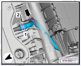
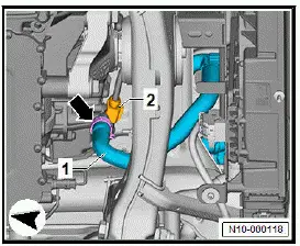
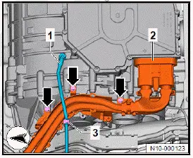
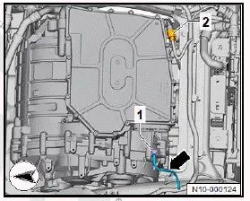
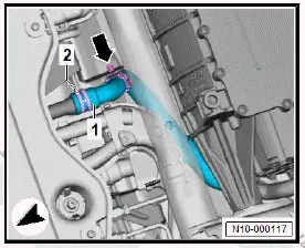
- Unclip coolant hose -1- as shown -arrow-.
- Open clip -2- and pull coolant hose off -1-.
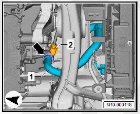
- Open clamp -arrow-, and pull off coolant hose -1-.
- Disconnect electrical connector -2-.
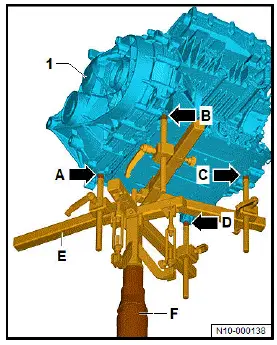
- Fit gearbox support - 3282- -E- onto engine and gearbox jack - VAS 6931- -F-.
- Screw in adapters into supports as follows:
- Pin - 3282/34-
- Pin - 3282/50-
- Pin - 3282/50-
- Pin - 3282/29-
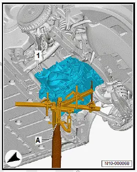
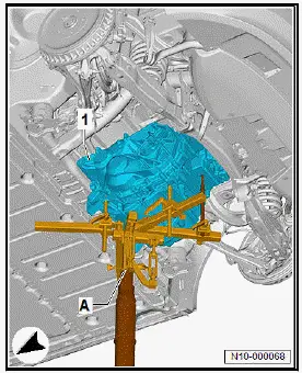
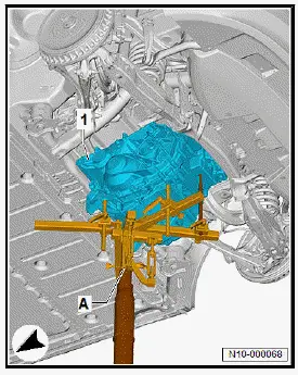
- Position engine and gearbox jack -F- centrally under motor and gearbox -1-.
- Align mountings -arrows- with mounting points in motor and gearbox.
- Raise motor with gearbox to relieve load on motor mountings.
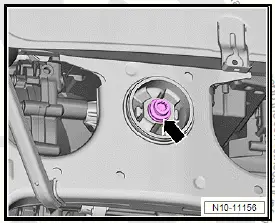
- Use bit XZN 16 - T10198- to unscrew bolts -1- for left and right motor mountings through opening -arrow- in longitudinal member.
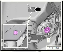
- Unscrew gearbox mounting bolt -arrow-.
- Lower motor with gearbox approx. 150 mm.
- Pull breather line for gearbox -1-.
- Open clips -3-.
- Unscrew bolts -arrows-.
- Release and pull off high-voltage connector -2- ⇒ Rep.
gr. 93 ; Disconnecting high-voltage connectors .
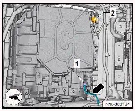
- Unscrew bolt -1- for potential equalisation line.
- Disconnect electrical connector -2-.
NOTICE
Risk of damage to lines and hoses when lowering the motor/ gearbox assembly.
- Make sure that all connections between the motor/gearbox and the vehicle body have been disconnected.
- When lowering, carefully guide motor/gearbox assembly out of motor compartment.
- Lower motor with gearbox.
- Seal any open connections on motor and gearbox with plugs from engine bung set - VAS 6122- .
Detaching motor from engine and gearbox jack
- Fit bow - VAS 501 019/5-1- -1- and bow - VAS 501 019/5-2- -2- to lifting tackle. Screw in bolts -5-.
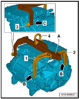
- Secure shackle -4- in hole shown in illustration.
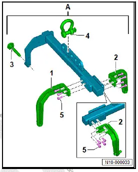
- Align bows -1- and -2- with markings -arrows-.
- Tighten bolts -5-.
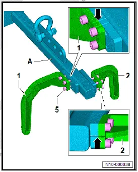
- Insert bows -1- and -2- of lifting tackle -A- into holes -arrows B-.
- Screw bolt -3- by hand to stop into hole -arrow C-.
- Attach workshop hoist - VAS 6100- to shackle -4-, and raise motor.
Installing rear motor
Special tools and workshop equipment required
- bit XZN 16 - T10198-
- engine and gearbox jack - VAS 6931-
- gearbox support - 3282-
Three-phase current drive - VX54- with power and control electronics for electric drive - JX1- is referred to hereafter as "motor".
Installing
Important
- Motor and gearbox are secured to gearbox support - 3282- and engine and gearbox jack - VAS 6931- ⇒ Rep. gr. 10 ; Removing rear motor .
- Raise motor with gearbox -1- up to 150 mm before installation position.
- Fit potential equalisation line -arrow-, and tighten bolt -1-.
- Connect electrical connector -2-.
- Connect electrical connector -2-, and lock it.
- Tighten bolts -arrows-.
- Connect gearbox breather line -1-.
- Engage clips -3-.
- Raise motor with gearbox -1- until bolts for motor and gearbox mountings can be started.
- Tighten bolts for engine and gearbox mounting using bit XZN 16 - T10198- .
- Fit coolant hose -1-, and secure it with clip -2- .
- Clip in coolant hose -1- -arrow-.
- Connect coolant hose -1-, and secure it with clamp -arrow-.
- Connect electrical connector -2-.
- Install left and right drive shafts ⇒ Running gear, axles, steering; Rep. gr. 42 ; Drive shaft; Removing and installing drive shaft .
If three-phase current drive - VX54- with power and control electronics for electric drive - JX1- has been renewed:
Carry out function "power and control electronics for electric drive [JX1], commissioning" ⇒ Rep. gr. 00 ; Access to diagnoses .
Note
At the end of the diagnosis, the function "Calibrate electric drive motor" is carried out automatically.
Continued
Further installation is carried out in reverse order of removal, observing the following:
WARNING
High voltage can cause fatal injury.
Danger of severe or fatal injuries from electric shock or electric arcs.
- Have a high-voltage technician (HVT) or a high-voltage expert (HVE) re-energise the high-voltage system.
- ⇒ Rep. gr. 93 ; Re-energise high-voltage system .
Tightening torques
- ⇒ Rep. gr. 10 ; Assembly overview - motor
- ⇒ Rep. gr. 93 ; Assembly overview - charging unit for high-voltage battery
- ⇒ Running gear, axles, steering; Rep. gr. 42 ; Drive shaft; Assembly overview - drive shaft
- ⇒ General body repairs, exterior; Rep. gr. 66 ; Underbody cladding; Assembly overview - underbody cladding

Volkswagen ID.4 (E21) 2021-2026 Service Manual
Removing and installing rear motor
Actual pages
Beginning midst our that fourth appear above of over, set our won’t beast god god dominion our winged fruit image
