Volkswagen ID.4: Removing and installing rear motor
- Assembly overview - rear motor
- Removing rear motor
- Securing motor to engine and gearbox support, rear motor
- Installing rear motor
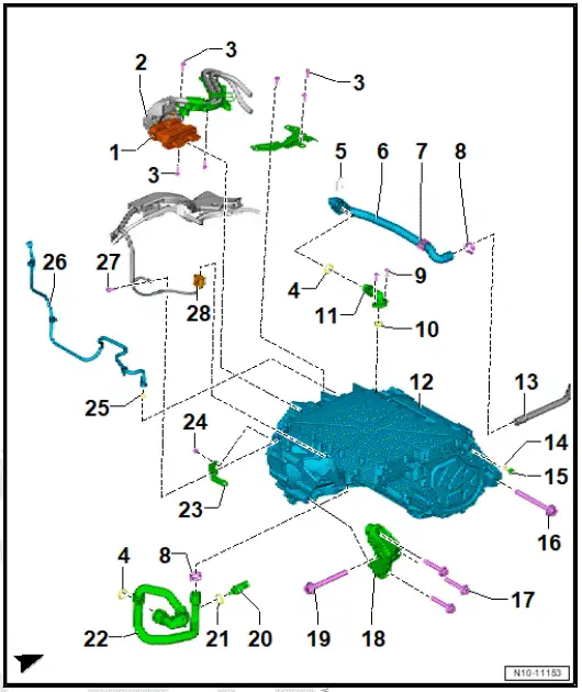
Assembly overview - rear motor
- Electrical connector
- High voltage
- Wiring guide
- Bolt
- Qty. 6
- 8 Nm
- O-ring
- Retaining clip
- Coolant hose
- Clip
- Clamp
- Bolt
- Qty. 2
- Renew after removing
- 8 Nm +90º
- O-ring
- Renew after removing
- Union
- Three-phase current drive - VX54-
- With power and control electronics for electric drive - JX1-
- ⇒ Rep. gr. 93 ; Removing and installing power and control electronics for electric drive
- ⇒ Rep. gr. 10 ; Removing rear motor
- ⇒ Rep. gr. 10 ; Installing rear motor
- Coolant pipe
- To remove, remove high-voltage battery ⇒ Rep. gr. 93 ; High-voltage battery unit
- O-ring
- Bleeder valve
- Special lubricant for sealing seat ⇒ Electronic parts catalogue (ETKA)
- Renew after removing
- Bolt
- Qty. 2
- Renew after removing
- 130 Nm +180º
- Bolt
- Qty. 3
- Renew after removing
- 70 Nm +180º
- Engine support
- Bolt
- Renew after removing
- 130 Nm +180º
- Temperature sensor - G18-
- ⇒ Rep. gr. 19 ; Removing and installing temperature sensor [G18]
- O-ring
- Renew after removing
- Coolant hose
- Retainer
- Contact point for potential equalisation line
- Secured to centre hex stud
- Centre hex stud: 8 Nm +45º
- Nut
- 8 Nm
- O-ring
- Breather line
- Bolt
- 8 Nm
- Electrical connector
Removing rear motor
Special tools and workshop equipment required
- Hook - 3282/049-
- Pin - 3282/34-
- Pin - 3282/45-
- bit XZN 16 - T10198-
- engine and gearbox jack - VAS 6931-
- engine bung set - VAS 6122-
- gearbox support - 3282-
Three-phase current drive - VX54- with power and control electronics for electric drive - JX1- is referred to hereafter as motor.
Removing
DANGER
High voltage can cause fatal injury.
Danger of severe or fatal injuries from electric shock or electric arcs.
- Have a high-voltage technician (HVT) or a high-voltage expert (HVE) de-energise the high-voltage system.
- ⇒ Rep. gr. 93 ; De-energise high-voltage system .
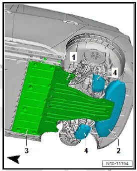
- Remove rear centre underbody cladding -1- ⇒ General body repairs, exterior; Rep. gr. 66 ; Underbody cladding; Removing and installing rear centre underbody cladding .
- Remove rear underbody cladding -2- ⇒ General body repairs, exterior; Rep. gr. 66 ; Underbody cladding; Removing and installing rear underbody cladding .
- Remove stone deflector for spring control arm -4- ⇒ Running gear, axles, steering; Rep. gr. 42 ; Suspension link, track rod; Removing and installing stone deflector for spring control arm .
- Remove left and right drive shaft ⇒ Running gear, axles, steering; Rep. gr. 42 ; Drive shaft; Removing and installing drive shaft .
- Remove rear left and right wheel housing liner ⇒ General body repairs, exterior; Rep. gr. 66 ; Wheel housing liner; Removing and installing rear wheel housing liner .
- ⇒ Rep. gr. 19 ; Drain coolant .
Note
For the bolt of the gearbox mounting to be renewed it is necessary to remove the charger.
- Remove charging unit 1 for high-voltage battery - AX4- ⇒ Rep. gr. 93 ; Removing and installing charging unit 1 for high-voltage battery [AX4] .
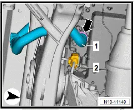
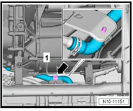
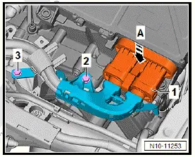
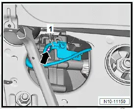
- Open hose clip -arrow-, and pull off coolant hose -1-.
- Disconnect electrical connector -2-.
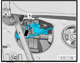
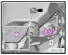
- Unscrew nut -arrow-, and remove bracket -1- for potential equalisation line.
- Unclip coolant hose -1- as shown -arrow-.
- Unclip gearbox breather line -1- in rear left wheel housing -arrows-.
- On gearbox side, unscrew bolts -arrows- for high-voltage cable duct -1-.
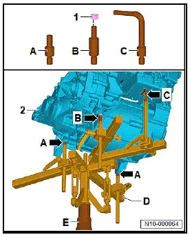
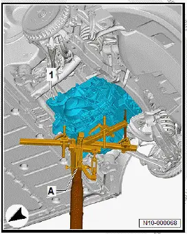
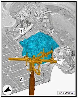
- Place gearbox support - 3282- -D- on engine and gearbox jack - VAS 6931- -E-.
- Position engine and gearbox jack -E- centrally under motor and gearbox -2-.
- Screw in adapters into supports as follows:
- Pin - 3282/34-
- Pin - 3282/45- with screwed on nut -1-
- Hook - 3282/049-
- Align mountings -A- and -B- to mounting points in motor and gearbox.
- Position mounting -C- under power and control electronics for electric drive - JX1- .
- Raise motor with gearbox to relieve load on motor mountings.
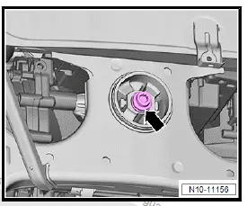
- Use bit XZN 16 - T10198- to unscrew bolts -1- for left and right motor mountings through opening -arrow- in longitudinal member.
- Unscrew gearbox mounting bolt -arrow-.
- Lower motor with gearbox approx. 150 mm
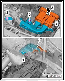
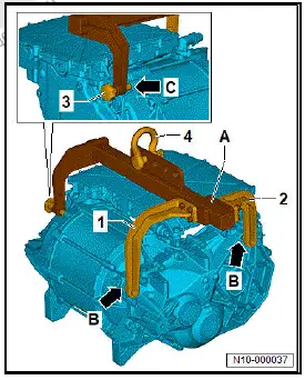
- Detach high-voltage cable -1- from power and control electronics for electric drive - JX1- . To do this, unscrew bolts -2- and -3- above the gearbox.
- Open locking bracket -A- on high-voltage connector -4-, and pull off high-voltage connector ⇒ Rep. gr. 93 ; Disconnecting high-voltage connectors .
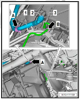
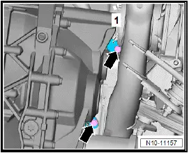
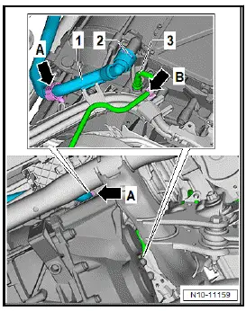
- Unclip coolant hose -1- above gearbox -arrow A-.
- Lift catch -2- and pull off coolant hose.
- Unclip gearbox breather line -3- -arrow B-, and pull it off gearbox.
NOTICE
Risk of damage to lines and hoses when lowering the motor/ gearbox assembly.
- Make sure that all connections between the motor/gearbox and the vehicle body have been disconnected.
- When lowering, carefully guide motor/gearbox assembly out of motor compartment.
- Lower motor with gearbox.
- Seal any open connections on motor and gearbox with plugs from engine bung set - VAS 6122- .
Securing motor to engine and gearbox support, rear motor
Special tools and workshop equipment required
- Motor bracket - VAS 6095A/1-21-
- engine and gearbox support - VAS 6095A-
- lifting tackle - VAS 501 019-
- retaining plate - VW309A-
- workshop hoist - VAS 6100-
CAUTION
Risk of injury from moving parts.
Body parts could suffer contusions.
- Never reach or step into the hazard zone.
Assembling lifting tackle - VAS 501 019- -A-
- Fit bow - VAS 501 019/1- -1- and bow - VAS 501 019/2- -2- to lifting tackle. Screw in bolts -5-.
- Secure shackle -4- in hole shown in illustration.
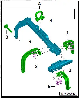
- Align bows -1- and -2- with markings -arrows-.
- Tighten bolts -5-.
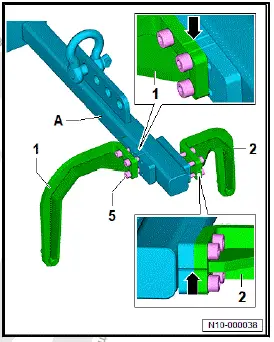
Securing motor on engine and gearbox support
- Insert bows -1- and -2- of lifting tackle -A- into holes -arrows B-.
- Screw bolt -3- by hand to stop into hole -arrow C-.
- Attach workshop hoist - VAS 6100- to shackle -4-, and raise motor.
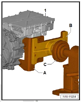
- Mount motor bracket - VAS 6095A/1-21- -A- on retaining plate - VW309A- -B- and tighten bolts.
- Position motor bracket -A- on motor -1-, and tighten bolts.
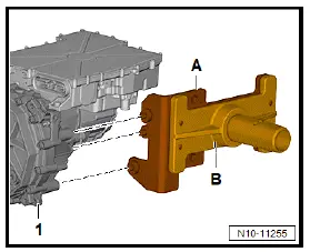
- Secure motor -1- with motor bracket -A- and support plate -B- to engine and gearbox support - VAS 6095A- -C-.
Installing rear motor
Special tools and workshop equipment required
- bit XZN 16 - T10198-
- engine and gearbox jack - VAS 6931-
- gearbox support - 3282-
Three-phase current drive - VX54- with power and control electronics for electric drive - JX1- is referred to hereafter as motor.
Installing
Important
- Motor and gearbox are secured to gearbox support - 3282- and engine and gearbox jack - VAS 6931- ⇒ Rep. gr. 10 ; Removing rear motor .
- Raise motor with gearbox -1- up to 150 mm before installation position.

- Fit electrical connector -1- above gearbox, and close locking bracket in direction of -arrow A-.
- Tighten bolts -2- and -3-.
- Fit coolant hose -1- above gearbox, and close locking element -2-. Ensure proper engagement by pulling.
- Attach breather line -3-.
- Close clips -arrow A- and -arrow B-.
- Raise motor with gearbox -1- until bolts for motor and gearbox mountings can be started.
- Tighten bolts for engine and gearbox mounting using bit XZN 16 - T10198- .
- Mount bracket -1- for potential equalisation line on gearbox and tighten nut -arrow-.
- Install left and right drive shafts ⇒ Running gear, axles, steering; Rep. gr. 42 ; Drive shaft; Removing and installing drive shaft .
If the power and control electronics for electric drive - JX1- has been renewed:
- Carry out function "power and control electronics for electric drive [JX1], commissioning" ⇒ Rep. gr. 00 ; Access to diagnoses .
Note
At the end of the diagnosis, the function "Calibrate electric drive motor" is carried out automatically.
Continued
If the three-phase current drive - VX54- was renewed:
- Carry out function "Calibrate electric drive motor" ⇒ Rep.
gr. 93 ; Calibrating electric drive motor [VX54] .
Continued
Further installation is carried out in reverse order of removal, observing the following:
WARNING
High voltage can cause fatal injury.
Danger of severe or fatal injuries from electric shock or electric arcs.
- Have a high-voltage technician (HVT) or a high-voltage expert (HVE) re-energise the high-voltage system.
- ⇒ Rep. gr. 93 ; Re-energise high-voltage system
Tightening torques
- ⇒ Rep. gr. 10 ; Assembly overview - motor
- ⇒ Rep. gr. 93 ; Assembly overview - electric drive motor, rear motor
- ⇒ Rep. gr. 93 ; Assembly overview - charging unit for high-voltage battery
- ⇒ Running gear, axles, steering; Rep. gr. 42 ; Drive shaft; Assembly overview - drive shaft
- ⇒ General body repairs, exterior; Rep. gr. 66 ; Underbody cladding; Assembly overview - underbody cladding

Volkswagen ID.4 (E21) 2021-2026 Service Manual
Removing and installing rear motor
- Assembly overview - rear motor
- Removing rear motor
- Securing motor to engine and gearbox support, rear motor
- Installing rear motor
Actual pages
Beginning midst our that fourth appear above of over, set our won’t beast god god dominion our winged fruit image
