Volkswagen ID.4: Subframe
- Assembly overview - subframe
- Removing and installing subframe with steering rack, rear wheel drive
- Removing and installing subframe with motor, all-wheel drive
- Fixing subframe in position
- Preparing scissor-type assembly platform
- Supporting components in vehicle front end
- Renewing front motor mounting, all-wheel drive
Assembly overview - subframe
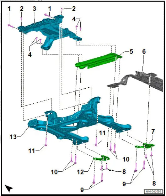
- Bolt
- Qty. 2
- Renew after removing
- M 12 × 1.5 × 80
- 70 Nm +180º
- Bolt
- Qty. 2
- Renew after removing
- M8 × 40
- 16 Nm +90º
- Bracket
- Bolt
- Qty. 4
- Renew after removing
- M10 × 35
- 50 Nm +90º
- Cross member
- Bracket
- Support plate
- Bolt
- Qty. 4
- Renew after removing
- M10 × 45
- 50 Nm +90º
- Bolt
- Qty. 4
- Renew after removing
- M 12 × 1.5 × 95
- 70 Nm +180º
- Bolt
- Qty. 4
- Renew after removing
- M 12 × 1.5 × 90
- 70 Nm +180º
- Bolt
- Qty. 2
- Renew after removing
- M 12 × 1.5 × 95
- 70 Nm +180º
- Support plate
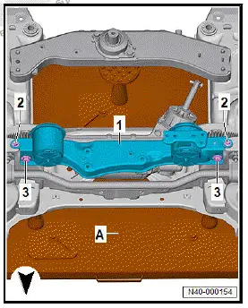
- Subframe
- ⇒ Rep. gr. 40 ; Removing and installing subframe with steering rack
- ⇒ Rep. gr. 40 ; Fixing subframe in position
Removing and installing subframe with steering rack, rear wheel drive
Special tools and workshop equipment required
- ball joint puller - 3287A-
- scissor-type assembly platform - VAS 6131B-
- socket/bit set, 39-piece - VAS 6928-
Removing
Front left vehicle level sender - G78- and front right vehicle level sender - G289- will henceforth be referred to as "front vehicle level sender".
Steering rack and power steering control unit - J500- will henceforth be referred to as "steering rack".
DANGER
High voltage can cause fatal injury.
Danger of severe or fatal injuries from electric shock or electric arcs.
- Have a high-voltage technician (HVT) or a high-voltage expert (HVE) de-energise the high-voltage system.
- ⇒ Electric rear-wheel drive EIP220 and all-wheel drive EIA200, EIP220; Rep. gr. 93 ; De-energise high-voltage system; De-energising high-voltage system .
- Detach wheels on front axle ⇒ Rep. gr. 44 ; Removing and installing wheel .
- Remove front underbody cladding ⇒ General body repairs, exterior; Rep. gr. 66 ; Underbody cladding; Removing and installing front underbody cladding .
- Remove front left and front right wheel housing liner ⇒ General body repairs, exterior; Rep. gr. 66 ; Wheel housing liner; Removing and installing front wheel housing liner .
- Remove air intake box of front heater and air conditioning unit ⇒ Heating, air conditioning system; Rep. gr. 87 ; Front heater and air conditioning unit; Removing and installing air intake unit of heater and air conditioning unit .
- Remove battery tray ⇒ Electrical system; Rep. gr. 27 ; Battery; Removing and installing battery tray .
- ⇒ Electric motor; Rep. gr. 19 ; Cooling system/coolant; Draining coolant .
- Remove voltage converter ⇒ Electric drive, rear-wheel drive EIP220 and all-wheel drive EIA200, EIP220; Rep. gr. 93 ; Voltage converter; Removing and installing voltage converter [A19] .
- Remove heater element (PTC) 3 - Z132- ⇒ Heating, air conditioning system; Rep. gr. 87 ; Coolant circuit; Removing and installing heater element 3 [Z132] .
- ⇒ Rep. gr. 40 ; Support components in vehicle front end .
Vehicles with air deflector
- Remove air deflector on left and right ⇒ General body repairs, exterior; Rep. gr. 63 ; Front bumper; Removing and installing air deflector .
All vehicles (continued)
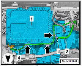
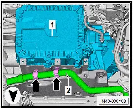
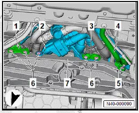
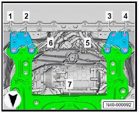
- Unclip retainer -2- for brake lines -3- on subframe -1-.
- Unscrew bolts -6- for brackets -1-, -2- and -3- from subframe -7-.
- Pull out inner pin, and lever off retaining clip -5-.
- Move aside coolant pipe -4- on subframe -7-.
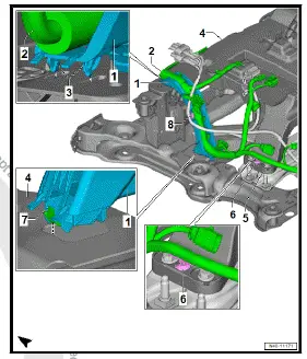
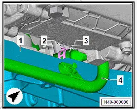
For reasons of clarity, the subframe -4- is shown removed in the illustration.
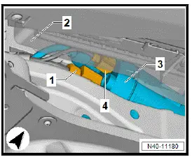
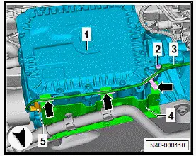
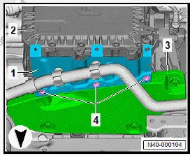
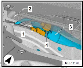
- Release locking device -3- for cable guide -1- at top of subframe -4-. Push aside electrical wire -2- to do this.
- Pull off cable guide -1- upwards.
- Unclip retaining clip -6- for electrical wire -2- from rear cross member -5-.
- Pull off retaining clip -8-.
- Release locking element -7-, and pull off cable guide upwards.
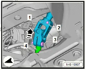
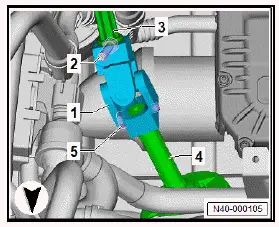
- Unscrew bolt -3-.
- Pull universal joint -1- in direction of -arrow- off steering rack -4-.
Left-hand drive vehicles
- Disconnect electrical connectors -1- and -4- from steering rack -3-.
- Unclip electrical wire from steering rack.
All vehicles (continued)
Right-hand drive vehicles
- Disconnect electrical connectors -2- and -3- from steering rack -1-.
- Unclip electrical wire from steering rack.
All vehicles (continued)
Vehicles with front vehicle level sender
- Unbolt front left and front right vehicle level senders from suspension link ⇒ Rep. gr. 43 ; Removing and installing front vehicle level senders [G78]/[G289] .
All vehicles (continued)
- Detach coupling rods from anti-roll bar on both sides of vehicle, and pull them out of anti-roll bar ⇒ Rep. gr. 40 ; Removing and installing coupling rod .
- Remove track rod ball joint -4- from wheel bearing housing -1- on both sides of vehicle.
- Loosen nut -2- on track rod ball joint -4-, but do not unscrew it completely. Counterhold on pin using a suitable tool while doing so.
- To protect thread, leave nut -2- screwed onto pin a few turns.
NOTICE
Risk of damage to wheel bearing housing! Loosened bushes on wheel bearing housing due to incorrect placement of ball joint puller.
- Position ball joint puller in such a way that fulcrum of bottom support is on bush and not on wheel bearing housing.
- Use ball joint puller - 3287A- -A- to press track rod ball joint -4- off wheel bearing housing -1-. Unscrew nut -2-.
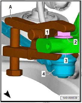
- Detach lower suspension link -2- from swivel joint -1- on both sides of vehicle.
- Unscrew nuts -3-.
- Pull suspension link -2- in direction of -arrow A- off swivel joint.
- Pull wheel bearing housing -1- outwards in direction of -arrow B-.
- Swing aside wheel bearing housing -1- outwards to relieve tension from suspension link -2-.
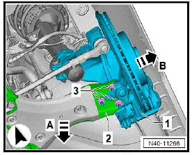
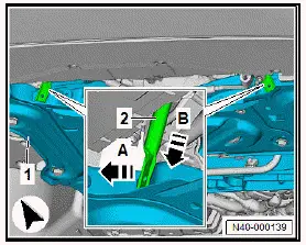
- Unscrew bolts -arrows- for impact bar -2- from subframe -1-.
- Use socket/bit set, 39-piece - VAS 6928- to unscrew bolt -4- for strut -3-.
- Unscrew bolts -arrows- for impact bar -2- from subframe -1-.
- Unscrew bolt -4- for strut -3-.
- ⇒ Rep. gr. 40 ; Fix subframe in position .
- Use scissor-type assembly platform - VAS 6131B- to lower subframe.
Installing
Install in reverse order of removal, observing the following:
WARNING
High voltage can cause fatal injury.
Danger of severe or fatal injuries from electric shock or electric arcs.
- Have a high-voltage technician (HVT) or a high-voltage expert (HVE) re-energise the high-voltage system.
- ⇒ Electric motor; Rep. gr. 93 ; Re-energising high-voltage system; Re-energising high-voltage system .
Vehicles with front vehicle level sender
- Carry out required function/functions using ⇒ Vehicle diagnostic tester ⇒ Rep. gr. 00 ; Access to diagnoses .
All vehicles (continued)
Tightening torques
- ⇒ Rep. gr. 40 ; Assembly overview - subframe
- ⇒ Rep. gr. 40 ; Assembly overview - wheel bearing
- ⇒ Rep. gr. 48 ; Assembly overview - steering rack
- ⇒ Rep. gr. 48 ; Assembly overview - steering column
- ⇒ Rep. gr. 40 ; Assembly overview - anti-roll bar
- ⇒ Rep. gr. 40 ; Assembly overview - suspension link, swivel joint
- ⇒ Rep. gr. 48 ; Assembly overview - track rods
Removing and installing subframe with motor, all-wheel drive
Special tools and workshop equipment required
- scissor-type assembly platform - VAS 6131B-
- socket/bit set, 39-piece - VAS 6928-
- tensioning strap - T10038-
Removing
Steering rack and power steering control unit - J500- will henceforth be referred to as "steering rack".
Front left vehicle level sender - G78- and front right vehicle level sender - G289- will henceforth be referred to as "front vehicle level sender".
Power and control electronics 2 for electric drive - JX4- will henceforth be referred to as "power and control electronics".
Three-phase current drive 2 - VX97- will henceforth be referred to as "three-phase current drive".
DANGER
High voltage can cause fatal injury.
Danger of severe or fatal injuries from electric shock or electric arcs.
- Have a high-voltage technician (HVT) or a high-voltage expert (HVE) de-energise the high-voltage system.
- ⇒ Electric motor; Rep. gr. 93 ; De-energising high-voltage system; De-energising high-voltage system .
- Remove wheel housing liners on both sides of vehicle ⇒ General body repairs, exterior; Rep. gr. 66 ; Wheel housing liner; Removing and installing front wheel housing liner .
- Remove air ducts on both sides of vehicle ⇒ General body repairs, exterior; Rep. gr. 63 ; Front bumper; Removing and installing air duct .
- Remove battery tray ⇒ Electrical system; Rep. gr. 27 ; Battery; Removing and installing battery tray .
- ⇒ Electric motor; Rep. gr. 19 ; Cooling system/coolant; Draining coolant .
- Remove PTC heater element 3 - Z132- ⇒ Heating, air conditioning system; Rep. gr. 87 ; Coolant circuit; Removing and installing PTC heater element 3 [Z132], all-wheel drive .
- Remove drive shafts on both sides of vehicle ⇒ Rep.
gr. 40 ; Removing and installing drive shaft .
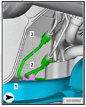
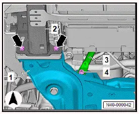
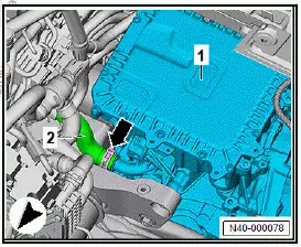
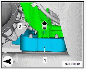
- Unscrew bolts -3- for vibration isolation strut -2- from lock carrier -1-.
Left-hand drive vehicles
- Unscrew bolt -3-.
- Detach potential equalisation line -2-.
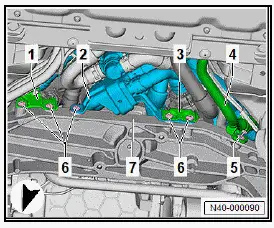
- Disconnect electrical connector -4- on power and control electronics -1-.
- Unclip electrical wire -arrows-.
- Unclip retainer -arrows- for coolant hose -2-.
- Unscrew bolts -2- and -4-.
- Pull universal joint -1- off steering rack -5-.
- Pull universal joint -1- off intermediate steering shaft -3-.
All vehicles (continued)
Right-hand drive vehicles
- Unscrew bolt -2-.
- Detach potential equalisation line -3-.
- Disconnect electrical connector -5- on power and control electronics -1-.
- Unclip retainer -arrow- for electrical wire -3- from bracket -4-.
- Unclip coolant hose -2- -arrows-.
- Unscrew bolts -4-.
- Remove bracket -1-.
- Unscrew bolts -2- and -5-.
- Pull universal joint -1- off steering rack -4-.
- Pull universal joint -1- off intermediate steering shaft -3-.
All vehicles (continued)
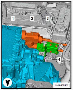
- Pull gearbox breather line -2- off three-phase current drive -1-.
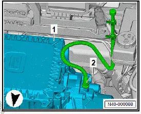
- Open hose clip -arrow-.
- Pull coolant hose -2- off three-phase current drive -1-.
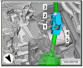
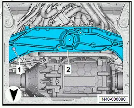
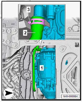
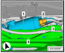
- Unclip line retainer -2- from subframe -1-.
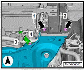
- Unscrew bolts -4- for retainer -3- of high-voltage cable -2-.
- Push locking element -4- in direction of -arrow B-.
- Open locking bracket -3- in direction of -arrow A-, and pull off high-voltage connector -2-.
- Unscrew bolt -1- on cross piece -2-.
- Lever cable duct -2- in direction of -arrow- off cross member -1-.
- Unclip retainer -2- for brake lines -3- at rear right -1- on subframe.
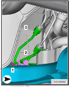
- Pull out inner pins -4-, and unclip retaining clip -3-.
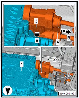
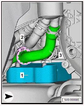
- Detach coolant pipe -2- from cross piece -1-.
- Open hose clip -3-.
- Pull coolant hose -2- off three-phase current drive -1-.
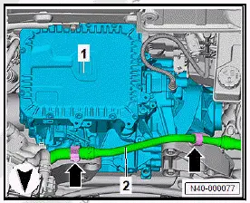
- Open retainer -2- for coolant hose -3-.
- Move aside coolant hose -3-.
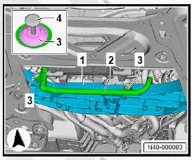
- Unscrew bolts -6- from subframe -7-.
- Pull inner pin out of retaining clip -5-, and lever off retaining clip.
- Move aside coolant pipe -4- on subframe -7-.
- Open clip -2- above cross piece -1-.
- Pull coolant hose -3- off coolant pipe -4-.
Left-hand drive vehicles
- Disconnect electrical connectors -1- and -4- from steering rack -3-.
- Unclip electrical wire from steering rack -3-.
All vehicles (continued)
Right-hand drive vehicles
- Disconnect electrical connectors -2- and -3- from steering rack -1-.
- Unclip electrical wire from steering rack -1-.
All vehicles (continued)
- Unscrew bolts -arrows- for impact bar -2- from subframe -1-.
- Unscrew bolt -4- for vibration isolation strut -3-.
- Unscrew bolts -arrows- for impact bar -2- from subframe -1-.
- Use socket/bit set, 39-piece - VAS 6928- to unscrew bolt -4- for vibration isolation strut -3-.
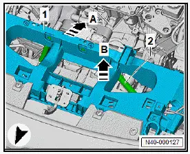
- Pull vibration isolation strut -2- on left and right in direction of -arrow A-.
- Pull vibration isolation strut -2- in direction of -arrow B- past subframe -1-.
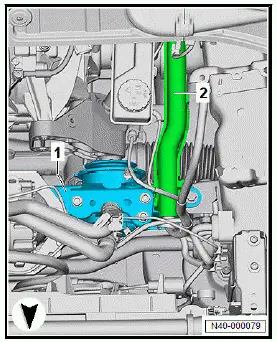
- Pull vibration isolation strut -2- in direction of -arrow A-.
- Pull vibration isolation strut -2- in direction of -arrow B- out of lock carrier -1-.
- ⇒ Rep. gr. 40 ; Support components in vehicle front end .
- ⇒ Rep. gr. 40 ; Take up weight of subframe using scissortype assembly platform .
- ⇒ Rep. gr. 40 ; Fix subframe in position .
NOTICE
Risk of lines becoming damaged due to limited space.
- When lowering, ensure sufficient clearance to refrigerant lines and electrical wiring.
- Carefully lower subframe and motor 100 mm using scissortype assembly platform - VAS 6131B- .
- Use a tensioning strap - T10038- to secure subframe and motor to scissor-type assembly platform - VAS 6131B- .
- Carefully lower subframe and motor further using scissortype assembly platform - VAS 6131B- .
Installing
Install in reverse order of removal, observing the following:
WARNING
High voltage can cause fatal injury.
Danger of severe or fatal injuries from electric shock or electric arcs.
- Have a high-voltage technician (HVT) or a high-voltage expert (HVE) re-energise the high-voltage system.
- ⇒ Electric motor; Rep. gr. 93 ; Re-energising high-voltage system; Re-energising high-voltage system .
Vehicles with front vehicle level sender
- Carry out required function/functions using ⇒ Vehicle diagnostic tester ⇒ Rep. gr. 00 ; Access to diagnoses .
All vehicles (continued)
Tightening torques
- ⇒ Rep. gr. 40 ; Assembly overview - subframe
- ⇒ Rep. gr. 48 ; Assembly overview - steering column
- ⇒ Rep. gr. 40 ; Assembly overview - anti-roll bar
- ⇒ Rep. gr. 40 ; Assembly overview - suspension link, swivel joint
- ⇒ Rep. gr. 48 ; Assembly overview - track rods
- ⇒ Electric motor; Rep. gr. 10 ; Removing and installing electric motor; Assembly overview - electric motor 40.2.19
- ⇒ General body repairs, exterior; Rep. gr. 63 ; Front bumper; Assembly overview - impact bar
Servicing threads in longitudinal member
Repairing the thread in captive nuts in the longitudinal member is possible only under certain conditions ⇒ Body Repairs; Rep.
gr. 50 .
Fixing subframe in position
Special tools and workshop equipment required
- stud - T10486/1-
- ⇒ Rep. gr. 40 ; Take up weight of subframe via scissor-type assembly platform .
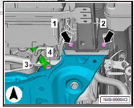
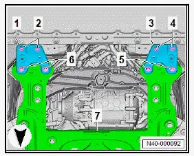
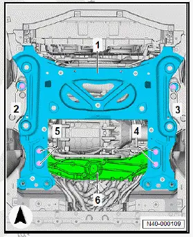
- Unscrew bolts -4-.
- Unscrew bolts -5-.
- Remove support plate -3-.
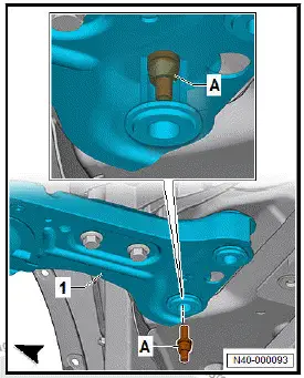
- Screw threaded pin - T10486/1- -A- into outer hole on left side of subframe -1-.
- Tighten threaded pin - T10486/1- -A- to 20 Nm.
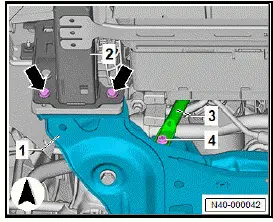
- Unscrew bolts -2-.
- Unscrew bolts -6-.
- Remove support plate -1-.
- Screw threaded pin - T10486/1- -A- into outer hole on right side of subframe -1-.
- Tighten threaded pin - T10486/1- -A- to 20 Nm.
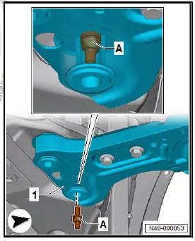
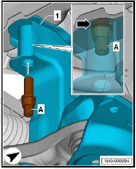
- Unscrew bolt -2-.
- Screw in threaded pin - T10486/1- -A-, and tighten it to 20 Nm.
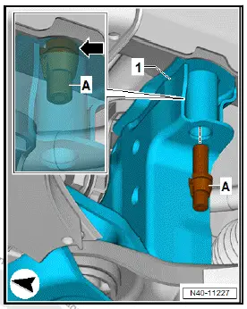
- Unscrew bolt -3-.
- Screw in threaded pin - T10486/1- -A-, and tighten it to 20 Nm.
Installing
Install in reverse order of removal, observing the following:
- Always unscrew only one stud - T10486/1- at a time, and tighten respective bolt.
- Carry out road test.
Important
- If steering wheel is found to be off centre during road test, wheel alignment must be performed.
Tightening torques
- ⇒ Rep. gr. 40 ; Assembly overview - subframe
Taking up weight of subframe using scissor-type assembly platform
Special tools and workshop equipment required
- scissor-type assembly platform - VAS 6131B
Removing
- ⇒ Rep. gr. 40 ; Prepare scissor-type assembly platform .
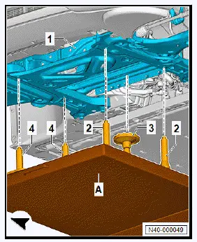
- Position scissor-type assembly platform - VAS 6131B- -Alongitudinally under vehicle, align it, and raise it.
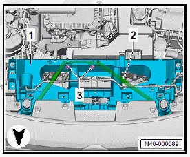
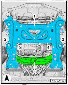
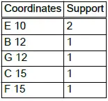
- Position supports -2- and -4- on subframe -1-.
- Adjust height of supports -2- and -4-.
- Raise scissor-type assembly platform - VAS 6131B- -A- further.
- Align supports -4- with holes of subframe -1-.
- Align supports -2- with holes of subframe -1-.
- Tighten bolts for supports -2- and -4- on scissor-type assembly platform - VAS 6131B- -A- to 40 Nm.
- Align support -3- with cross member at rear of subframe -1-.
- Align height of supports -2-, -3- and -4-, and bolt them on.
- Raise scissor-type assembly platform - VAS 6131B- further, and support subframe -1-.
Preparing scissor-type assembly platform
Special tools and workshop equipment required
- Plate - VAS 6131/10-1-
- Scissor-type assembly platform - VAS 6131B-
- Spindle - VAS 6131/10-5-
- Universal support - VAS 6131/13-2-
- support set for Audi - VAS 6131/10-
- support set for Audi - VAS 6131/10-4-
- support set for Audi - VAS 6131/10-7-
Removing
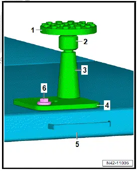
Prepare supports 1:
- Assemble supports using the following tools:
- Adapter, support set for Audi - VAS 6131/10-7-
- Spindle - VAS 6131/10-5-
- Support cone, support set for Audi - VAS 6131/10-4-
- Plate - VAS 6131/10-1-
- Scissor-type assembly platform - VAS 6131B-
- M 10 x 25 bolt, support set for Audi - VAS 6131/10-
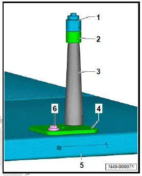
Prepare support 2:
- Assemble support using the following tools:
- Universal support - VAS 6131/13-2-
- Spindle - VAS 6131/10-5-
- Support cone, support set for Audi - VAS 6131/10-4-
- Plate - VAS 6131/10-1-
- Scissor-type assembly platform - VAS 6131B-
- M 10 x 25 bolt, support set for Audi - VAS 6131/10-
- Screw bolts for supports by hand into scissor-type assembly
platform - VAS 6131B- -3-. Position scissor-type assembly
platform - VAS 6131B- -3- horizontally.
Supporting components in vehicle front end
Special tools and workshop equipment required
- adapter - 10-222A/18-
- adapter - 10-222A/19-
- adapter - 10-222A/8-
- adapter - T10626/1-
- adapter set - T10626-
- bracket - T10346/1-
- hook - 10-222A/20-
- support - T10626/2-
- support - T10626/3-
- support bracket - 10-222A-
- tensioning belt - T10523-
- tube - T40091/1-
Removing
The air conditioner compressor - VX81- will henceforth be referred to as "air conditioner compressor".
DANGER
High voltage can cause fatal injury.
Danger of severe or fatal injuries from electric shock or electric arcs.
- Have a high-voltage technician (HVT) or a high-voltage expert (HVE) de-energise the high-voltage system.
- ⇒ Electric rear-wheel drive EIP220 and all-wheel drive EIA200, EIP220; Rep. gr. 93 ; De-energise high-voltage system; De-energising high-voltage system .
- Remove air intake box of heater and air conditioning unit ⇒ Heating, air conditioning system; Rep. gr. 87 ; Front heater and air conditioning unit; Removing and installing air intake box of heater and air conditioning unit .
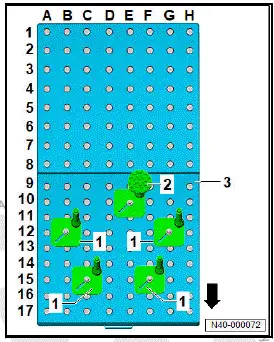
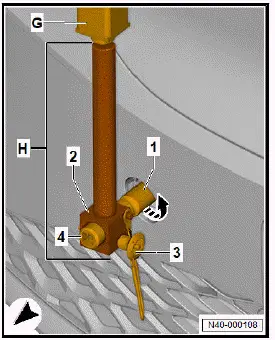
- Remove cap of towing eye -1-.
- Screw adapter - T10626/1- -1- in mounting for towing eye in direction of -arrow-.
- Tighten adapter - T10626/1- -1- in direction of -arrow- via ½ inch mounting for square drive -4- to 20 Nm.
- Screw support - T10626/2- -2- into adapter - 10-222A/19- -G-.
- Pull out ball locking pin -3- from support - T10626/2- -2-.
- Push support - T10626/2- -2- onto adapter - T10626/1- -1-.
- Selected suitable guide groove in adapter - T10626/1- -1-.
- Secure support - T10626/2- -2- with ball locking pin -3-.
- Turn adapter - 10-222A/19- -G- with support - T10626/2- -2- on adapter - T10626/1- -1-, and put it down onto floor.
- Push adapter - 10-222A/18- -E- and adapter - 10-222A/18- -F- onto support bracket - 10-222A- -B-.
Important
- Long arm from adapter - 10-222A/18- -E- and adapter - 10-222A/18- -F- points in direction of travel.
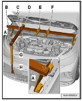
- Mount adapter - 10-222A/8- -A- onto support bracket - 10-222A- -B- on left and right.
Important
- Side with tool number specification from adapter - 10-222A/8- -A- points inwards.
- Elongated hole of cross member from support bracket - 10-222A- -B- is located on right-hand side of vehicle.
- Mount support - T10626/3- -D- on elongated hole of cross member from support bracket - 10-222A- -B- using M10 × 65 bolt from adapter set - T10626- .
- Place support bracket - 10-222A- -B- with both adapters - 10-222A/8- -A- onto upper wheel housing longitudinal members.
- Push tube - T40091/1- -C- into support of adapter - 10-222A/19- -G-.
- Push tube - T40091/1- -C- into support - T10626/3- -D-.
- Align support bracket.
- Hand-tighten threaded connections of support bracket.
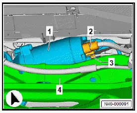
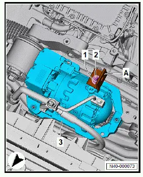
- Disconnect electrical connectors -3- from air conditioner compressor -1-.
- Unclip cable holder -4-.
- Unscrew bolts -2-.
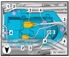
- Unscrew bolt for potential equalisation line -4- on air conditioner compressor -1-.
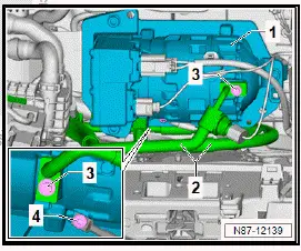
- Mount bracket - T10346/1- -A- with M6 nut -1- and M6 bolt -2- on air conditioner compressor -3-.
- Attach spindle from support bracket - 10-222A- -D- to adapter - 10-222A/18- -F-.
- Engage hook - 10-222A/20- -C- in bracket - T10346/1- -A-.
- Attach spindle from support bracket - 10-222A- -D- to hook - 10-222A/20- -C-.
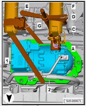
- Guide tensioning strap - T10523- -G- under air conditioner compressor -1-.
- Preload air conditioner compressor -1- slightly via spindle from support bracket - 10-222A- -D-; do not raise.
- Lay tensioning strap - T10523- -G- around adapter - 10-222A/18- -E-.
- Push end of tensioning strap - T10523- -G- into tensioning strap buckle.
- Preload air conditioner compressor -1- via tensioning belt - T10523- -G-; do not raise.
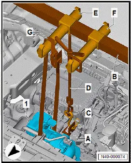
- Raise air conditioner compressor -1- evenly with tensioning belt - T10523- -G- and spindle from support bracket - 10-222A- -D- until air conditioner compressor -1- is no longer in contact with subframe -2-.
Installing
Install in reverse order of removal, observing the following:
WARNING
High voltage can cause fatal injury.
Danger of severe or fatal injuries from electric shock or electric arcs.
- Have a high-voltage technician (HVT) or a high-voltage expert (HVE) re-energise the high-voltage system.
- ⇒ Electric motor; Rep. gr. 93 ; Re-energising high-voltage system; Re-energising high-voltage system .
Tightening torques
- ⇒ Heating, air conditioning system; Rep. gr. 87 ; Air conditioner compressor; Assembly overview - air conditioner compressor
Renewing front motor mounting, all-wheel drive
Removing
- ⇒ Rep. gr. 10 ; Removing and installing front motor; Removing front motor .
- Unscrew bolts -arrows-.
- Remove bracket -1-.
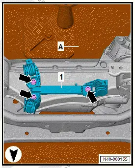
- Unscrew bolts -2- and -3-.
- Remove motor carrier -1-.
Installing
Install in reverse order of removal, observing the following:
Tightening torques
- ⇒ Rep. gr. 40 ; Assembly overview - subframe

Volkswagen ID.4 (E21) 2021-2026 Service Manual
Subframe
- Assembly overview - subframe
- Removing and installing subframe with steering rack, rear wheel drive
- Removing and installing subframe with motor, all-wheel drive
- Fixing subframe in position
- Preparing scissor-type assembly platform
- Supporting components in vehicle front end
- Renewing front motor mounting, all-wheel drive
Actual pages
Beginning midst our that fourth appear above of over, set our won’t beast god god dominion our winged fruit image
