Volkswagen ID.4: Suspension strut, upper suspension link
- Assembly overview - suspension strut
- Removing and installing suspension strut
- Removing and installing spring
Assembly overview - suspension strut
The overview is shown for the left side of the vehicle as an example.
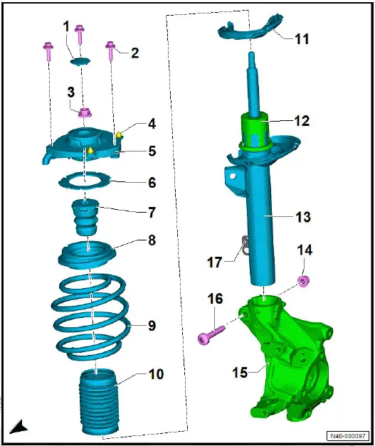
- Cover
- Bolt
- Qty. 3
- Renew after removing
- M8 x 35
- 20 Nm +90º
- Nut
- Renew after removing
- 60 Nm
- Guide
- Suspension strut mounting
- Plate
- Bump stop
- Depending on equipment/ version
- Allocation ⇒ Electronic parts catalogue (ETKA)
- Deep groove ball thrust bearing
- Spring
- Allocation ⇒ Electronic parts catalogue (ETKA)
- ⇒ Rep. gr. 40 ; Removing and installing spring
- Protective sleeve
- Spring seat
- Protective sleeve
- Shock absorbers
- Depending on equipment/version, with or without front left shock absorber damping adjustment valve - N336- and front right shock absorber damping adjustment valve - N337-
- Allocation ⇒ Electronic parts catalogue (ETKA)
- ⇒ Rep. gr. 40 ; Removing and installing suspension strut
- Nut
- Renew after removing
- M 12 x 1.5
- Wheel bearing housing
- Allocation ⇒ Electronic parts catalogue (ETKA)
- ⇒ Rep. gr. 40 ; Assembly overview - wheel bearing
- Bolt
- Renew after removing
- M 12 x 1.5 x 80
- 70 Nm +180º
- Guide
Removing and installing suspension strut
Special tools and workshop equipment required
- engine and gearbox jack - VAS 6931-
- spreader device - VAS 751 003-
- support - VAS 6931/1-
- suspension strut support clamp - V.A.G 1752/20-
- suspension strut tensioner - VAS 751 005-
Removing
Front left speed sensor - G47- and front right speed sensor - G45- will henceforth be referred to as "front speed sensor".
Front left vehicle level sender - G78- and front right vehicle level sender - G289- will henceforth be referred to as "front vehicle level sender".
Front left shock absorber damping adjustment valve - N336- and front right shock absorber damping adjustment valve - N337- will henceforth be referred to as "shock absorber damping adjustment valve".
Removal and installation are described for the left side of vehicle as an example.
- Prepare suspension strut tensioner - VAS 751 005- according to ⇒ operating instructions .
- Remove wheel ⇒ Rep. gr. 44 ; Removing and installing wheel .
Vehicles with front vehicle level sender
- Remove front vehicle level sender from suspension link ⇒ Rep. gr. 43 ; Removing and installing front vehicle level sender [G78]/[G289] .
All vehicles (continued)
- Unscrew nut of coupling rod from suspension strut ⇒ Rep. gr. 40 ; Removing and installing coupling rod .
- Pull coupling rod off suspension strut.
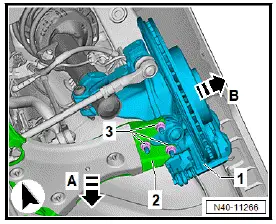
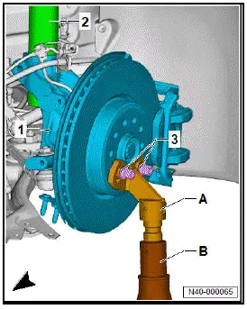
- Unscrew nuts -3-.
- Pull off suspension link -2- in direction of -arrow A-
- Pull wheel bearing housing -1- in direction of -arrow B-.
- Remove wiper motor control unit - J400- ⇒ Electrical system; Rep. gr. 92 ; Windscreen wiper system; Removing and installing windscreen wiper motor [V] .
Vehicles with shock absorber damping adjustment valve
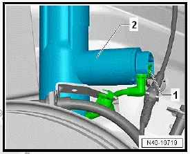
- Disconnect electrical connector -1- on shock absorber damping adjustment valve -2-.
All vehicles (continued)
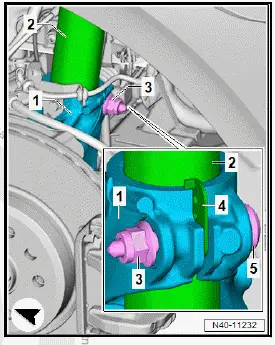
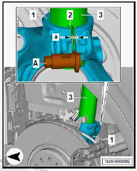
- Unscrew nut -3-.
- Pull bolt -5- out of wheel bearing housing -1-.
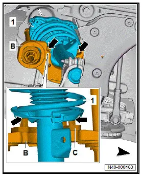
NOTICE
Risk of damage to the suspension strut -3- if the guide -2- breaks off.
- Do not twist the suspension strut -3- when loosening.
- Do not turn the wheel bearing housing -1- against the guide -2-.
- Insert spreader device - VAS 751 003- -A- into slot of wheel bearing housing -1-.
- Spread wheel bearing housing -1- using spreader device - VAS 751 003- -A-. While doing this, turn at hexagon -Bof spindle while counterholding at level surface -C- using suitable tools.
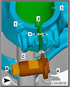
NOTICE
Risk of damage to the wheel bearing housing by spreading it too far.
- Do not spread the wheel bearing housing further than the specified dimension.
- Spread wheel bearing housing -1- using spreader device - VAS 751 003- -A-.
Important
- Dimension -a- must be max. 7.8 mm.
- Do not turn further than end stop of spreader device - VAS 751 003- -A-.
- Unscrew bolt -2- from wheel bearing housing -7-.
- Secure support - VAS 6931/1- -A- using two wheel bolts -2-.
- Place engine and gearbox jack - VAS 6931- -B- under support - VAS 6931/1- -A-.
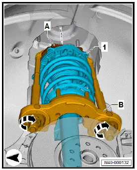
- Secure and support wheel bearing housing -1-.
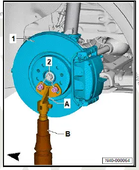
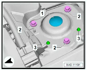
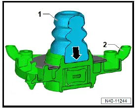
- Remove cap -1-.
- Unscrew suspension strut mounting bolts -2-
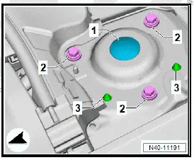
- Lower wheel bearing housing -1- with engine and gearbox jack - VAS 6931- -B- and support - VAS 6931/1- -A- until suspension strut -2- is free.
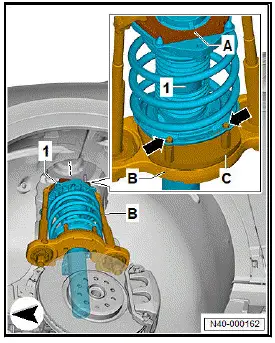
- Assemble suspension strut tensioner - VAS 751 005- according to ⇒ operating instructions .
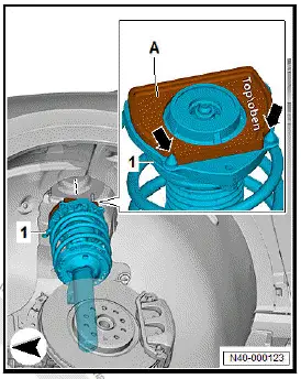
- Place support ring - VAS 751 005/3- -A- on suspension strut -1-.
Important
- Recesses must be located in guides -arrows-.
- Lettering "Top/oben" must point upwards.
- Position suspension strut tensioner - VAS 751 005- at suspension strut -1-.
- Attach hooks -B- of suspension strut tensioner - VAS 751 005- to support ring - VAS 751 005/3- -A-.
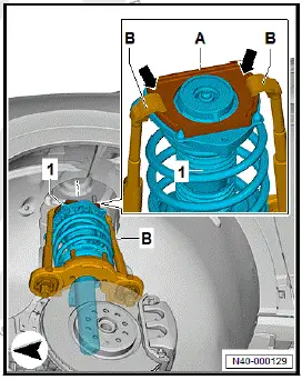
Important
- Make sure that hooks -B- of suspension strut tensioner - VAS 751 005- properly engage in support ring - VAS 751 005/3- -A-.
- Insert pins -arrows- of support plate - VAS 751 005/2- -Cinto suspension strut -1-.
Important
- Pins -arrows- of support plate - VAS 751 005/2- -C- must be located in guides of suspension strut -1-.
- Position rods -arrows- of support plate - VAS 751 005/2- -Con suspension strut -1-.
Important
- Rods -arrows- of support plate - VAS 751 005/2- -C- must be in contact with suspension strut -1-.
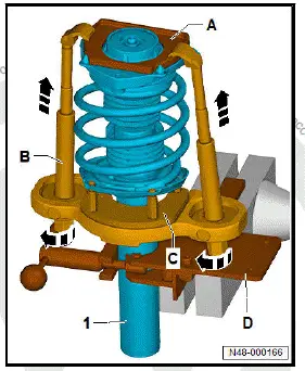
- Turn spindles of suspension strut tensioner - VAS 751 005- -B- in direction of -arrow- evenly and alternately.
- Turn spindles of suspension strut tensioner - VAS 751 005- -B- in direction of -arrow- until there is enough space for removal of suspension strut -1-.
Important
- Procedure must be stopped when there are no more threads on spindle.
- Spring coils must not be in contact with each other.
- Clamp suspension strut support clamp - V.A.G 1752/20- -Din a vice.
- Clamp suspension strut -1- in suspension strut support clamp - V.A.G 1752/20- -D-.
- Measure and note distance between support ring - VAS 751 005/3- -A- and support plate - VAS 751 005/2- -C-.
CAUTION
Components are under tension.
Loosening threaded connection may cause injury.
- Do not loosen nut of piston rod on suspension strut.
- Turn spindles of suspension strut tensioner - VAS 751 005- -B- in direction of -arrow-.
- Release tension in suspension strut tensioner - VAS 751 005- -B- in direction of -arrow-.
- Remove suspension strut tensioner - VAS 751 005- -B-.
Installing
Install in reverse order of removal, observing the following:
- Adjust distance between support ring - VAS 751 005/3- and support plate - VAS 751 005/2- via spindles according to noted values.
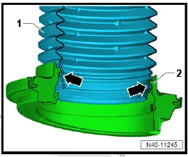
- The aid of an additional person is required for the subsequent work steps.
- Guides -3- must be properly seated in body.
- Tighten bolts -2-.
Vehicles with vehicle level sender
- Perform necessary functions with ⇒ Vehicle diagnostic tester ⇒ Rep. gr. 00 ; Access to diagnoses .
All vehicles (continued)
Tightening torques
- ⇒ Rep. gr. 40 ; Assembly overview - suspension strut
- ⇒ Rep. gr. 40 ; Assembly overview - anti-roll bar
- ⇒ Rep. gr. 40 ; Assembly overview - suspension link, swivel joint
- ⇒ Brake system; Rep. gr. 46 ; Front brake; Assembly overview - front brake
Removing and installing spring
Special tools and workshop equipment required
- Ring spanner insert - V.A.G 1332/7-
- Spring tensioner - V.A.G 1752/1-
- Torque wrench - V.A.G 1332-
- shock absorber set - T10001-
- spring retainer - V.A.G 1752/4-
- spring tensioner - V.A.G 1752/1-
- suspension strut support clamp - V.A.G 1752/20-
- suspension strut support clamp - V.A.G 1752/20-
Removing
- Remove suspension strut ⇒ Rep. gr. 40 ; Removing and installing suspension strut .
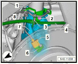
- Clamp suspension strut support clamp - V.A.G 1752/20- -5- in a vice -6-.
- Clamp suspension strut -3- in suspension strut support clamp - V.A.G 1752/20- -5-.
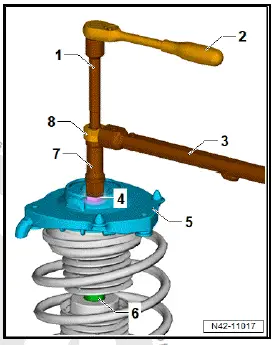
- Assemble spring compressor - V.A.G 1752/1- -1- with spring retainer - V.A.G 1752/4- -2-.
- Apply spring compressor - V.A.G 1752/1- -1- with spring retainer - V.A.G 1752/4- -2- at spring -4-.
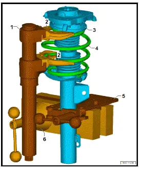
- Make sure that spring -2- is properly seated in spring retainer - V.A.G 1752/4- -4- -arrow-.

- Use spring tensioner - V.A.G 1752/1- -11- to preload spring -8- until suspension strut mounting -6- is completely unloaded.
- Apply tools from shock absorber set - T10001- .
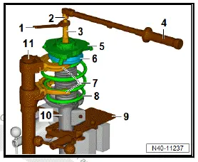
- Ratchet - T10001/11-
- Extension - T10001/8-
- Socket - T10001/5-
- Torque wrench
- Suspension strut mounting
- Deep groove ball thrust bearing
- Spring retainers - V.A.G 1752/4-
- Spring
- Suspension strut support clamp - V.A.G 1752/20-
- Suspension strut
- Spring tensioner - V.A.G 1752/1-
- Loosen threaded connection. When doing this, counterhold at piston rod with tools.
- Unscrew nut.
- Remove suspension strut mounting -5- and deep groove ball thrust bearing -6-.
- Remove spring -8-.
Installing
Install in reverse order of removal, observing the following:
Installation position of attachments
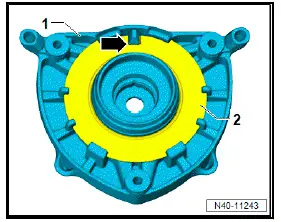
- Insert plate -2- into suspension strut mounting -1- so that plate is located beneath hooks of suspension strut mounting.
Important
- Guide -arrow- must be seated in recess of plate -2-.
- Press bump stop -1- into suspension strut mounting -2-.
Important
- Bump stop -1- must rest against suspension strut mounting -2- -arrow-.
- Insert protective sleeve -1- in deep groove ball thrust bearing -2-.
Important
- Protective sleeve -1- must be properly engaged -arrows-.
All vehicles (continued)
- Insert spring seat -3- into shock absorber -2-.
- Fit spring -1- with spring tensioner - V.A.G 1752/1- onto spring seat -3- at bottom.
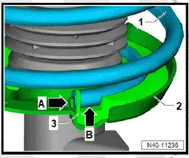
Important
- End of spring coil -arrow B- must be in contact with limit stop -arrow A-.
NOTICE
Noises may occur if the suspension strut mounting is not assembled correctly in relation to the thrust bearing.
- Observe installation position of suspension strut mounting in relation to deep groove ball thrust bearing when assembling.
- Fit deep groove ball thrust bearing -2- onto spring -3-.
- Align suspension strut mounting -1- with thrust bearing -2-.
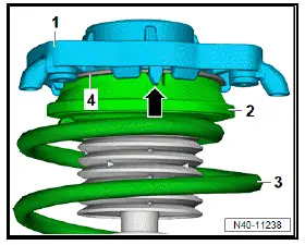
Important
- Guide of suspension strut mounting -1- must be located in recess -arrow- of deep groove ball thrust bearing -2-.
- Suspension strut mounting -1- must be folded over collar of deep groove ball thrust bearing -2- all around.
- Make sure that plate -4- is correctly seated.
- Tighten nut -4- on piston rod -6-, and counter-hold at piston rod with tool.
- Extension - T10001/8-
- Commercially available ratchet
- Torque wrench - V.A.G 1332-
- Nut
- Suspension strut mounting
- Piston rod
- Socket - T10001/5-
- Ring spanner insert - V.A.G 1332/7-
- Relieve tension on spring tensioner - V.A.G 1752/1- , and remove it from spring.
- Remove suspension strut from suspension strut support clamp - V.A.G 1752/20- .
Tightening torques
- ⇒ Rep. gr. 40 ; Assembly overview - suspension strut

Volkswagen ID.4 (E21) 2021-2026 Service Manual
Suspension strut, upper suspension link
- Assembly overview - suspension strut
- Removing and installing suspension strut
- Removing and installing spring
Actual pages
Beginning midst our that fourth appear above of over, set our won’t beast god god dominion our winged fruit image
