Volkswagen ID.4: Lower suspension link, swivel joint
- Assembly overview - suspension link, swivel joint
- Removing and installing suspension link
- Removing and installing swivel joint
- Removing and installing stone deflector for suspension link
- Renewing front suspension link bush
- Renewing suspension link bush, rear
Assembly overview - suspension link, swivel joint
The overview is shown for the left side of the vehicle as an example.
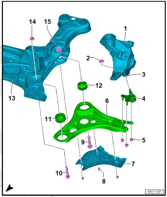
- Wheel bearing housing
- ⇒ Rep. gr. 40 ; Assembly overview - wheel bearing
- ⇒ Rep. gr. 40 ; Removing and installing wheel bearing housing
- Nut
- Renew after removing
- M12 × 1.5
- Nut M12: 60 Nm
- Nut M14: 110 Nm
- Bush
- Swivel joint
- ⇒ Rep. gr. 40 ; Removing and installing swivel joint
- Nut
- Qty. 3
- Renew after removing
- Nut M10: 40 Nm + 45º
- Nut M12: 100 Nm
- Suspension link
- ⇒ Rep. gr. 40 ; Removing and installing suspension link
- Stone deflector for suspension link
- ⇒ Rep. gr. 40 ; Removing and installing stone deflector for suspension link
- Spreader rivet
- Qty. 3
- Bolt
- Renew after removing
- M14 × 1.5 × 85
- 130 Nm +180º
- Bolt
- Renew after removing
- M 12 × 1.5 × 80
- 70 Nm +180º
- Suspension link mounting, front
- ⇒ Rep. gr. 40 ; Renewing front suspension link bush
- Suspension link mounting, rear
- ⇒ Rep. gr. 40 ; Renewing suspension link bush, rear
- Subframe
- ⇒ Rep. gr. 40 ; Assembly overview - subframe
- Nut
- Renew after removing
- M12 × 1.5
- Weld nut
Removing and installing suspension link
Front left speed sensor - G47- and front right speed sensor - G45- will henceforth be referred to as "speed sensor".
Front left vehicle level sender - G78- and front right vehicle level sender - G289- will henceforth be referred to as "vehicle level sender".
Removal and installation are described for the left side of vehicle as an example
Removing
- Remove wheel ⇒ Rep. gr. 44 ; Removing and installing wheel .
- Remove stone deflector for suspension link ⇒ Rep. gr. 40 ; Removing and installing stone deflector for suspension link .
Vehicles with vehicle level sender
- Remove vehicle level sender from suspension link ⇒ Rep. gr. 43 ; Removing and installing front vehicle level sender [G78]/[G289] .
All vehicles (continued)
- Unscrew nuts -3-.
- Pull suspension link -2- downwards -arrow A- off swivel joint.
- Pull wheel bearing housing -1- outwards in direction of -arrow B-.
- Swing wheel bearing housing -1- outwards to relieve tension from suspension link -2-.
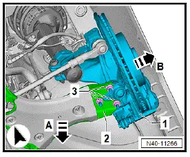
- Unscrew bolt -4- while counter-holding at nut -2-.
- Unscrew bolt -5-.
- Pull suspension link -1- out of subframe -3-.
Installing
Install in reverse order of removal, observing the following:
Vehicles with vehicle level sender
- Carry out required function/functions using ⇒ Vehicle diagnostic tester ⇒ Rep. gr. 00 ; Access to diagnoses .
All vehicles (continued)
Tightening torques
- ⇒ Rep. gr. 40 ; Assembly overview - suspension link, swivel joint
Removing and installing swivel joint
Special tools and workshop equipment required
- ball joint puller - 3287AFront
left vehicle level sender - G78- and front right vehicle level sender - G289- will henceforth be referred to as "vehicle level sender".
Removal and installation are described for the left side of vehicle as an example.
Tools and auxiliary equipment required:
- Torx T40, commercially available
Removing
Vehicles with all-wheel drive:
- Loosen threaded connection of drive shaft ⇒ Running gear, axles, steering; Rep. gr. 40 ; Drive shafts; Loosening and tightening threaded connections of drive shaft .
All vehicles (continued)
- Remove wheel ⇒ Rep. gr. 44 ; Removing and installing wheel .
- Remove stone deflector for suspension link ⇒ Rep. gr. 40 ; Removing and installing stone deflector for suspension link .
Vehicles with vehicle level sender
- Unbolt left vehicle level sender from suspension link ⇒ Rep.
gr. 43 ; Removing and installing front vehicle level sender [G78]/[G289] .
All vehicles (continued)
Vehicles with all-wheel drive:
- Loosen threaded connection of drive shaft.
- Press drive shaft out of wheel bearing unit ⇒ Running gear, axles, steering; Rep. gr. 40 ; Drive shaft; Removing and installing drive shaft .
All vehicles (continued)
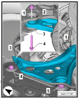
- Unscrew nuts -3-.
- Pull suspension link -2- in direction of -arrow A- off swivel joint.
- Pull wheel bearing housing -1- in direction of -arrow B-.
- Swing wheel bearing housing -1- outwards to relieve tension from suspension link -2-.
- Push suspension link upwards.
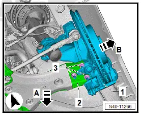
- Loosen nut -4- of swivel joint -2- without unscrewing it completely.
Important
- To protect threads, nut -4- must remain screwed onto pin a few turns.
- Counterhold with commercially available Torx T40 in the process.
NOTICE
Damage to wheel bearing housing from loosened bushes due to incorrectly applied ball joint puller.
- Ball joint puller must be supported on bush and not on wheel bearing housing.
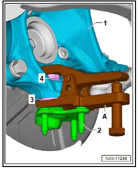
- Fit ball joint puller - 3287A- -A- with bottom support against bush -3-.
- Press swivel joint -2- off wheel bearing housing -1- using ball joint puller - 3287A- -A-.
- Unscrew nut -4-.
Installing
Install in reverse order of removal, observing the following
Vehicles with front vehicle level sender
- Carry out required function/functions using ⇒ Vehicle diagnostic tester ⇒ Rep. gr. 00 ; Access to diagnoses .
All vehicles (continued)
Tightening torques
- ⇒ Rep. gr. 40 ; Assembly overview - suspension link, swivel joint
Removing and installing stone deflector for suspension link
Removing
Removal and installation are described for the left side of vehicle as an example.
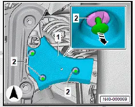
Spreader rivets with pins for pressing inwards
- Press pins -arrows- in all spreader rivets -2- inwards.
- Lever off spreader rivets with commercially available plastic wedge, and detach stone deflector for front suspension link -1-.
- Remove pins -arrows- from suspension link from above.
All vehicles (continued)
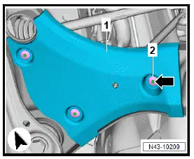
Spreader rivets with pins for pulling out
- Pull out pins -arrows- of all spreader rivets -2-.
- Lever off spreader rivets using commercially available plastic wedge, and detach stone deflector for suspension link -1-.
All vehicles (continued)
Installing
Install in reverse sequence of removal.
Renewing front suspension link bush
Special tools and workshop equipment required
- Assembly tool - T10642-
- centring pin - T10642/3-
- press tool - VW412-
- thrust piece - T10642/4-
- thrust plate - VW401ARenewal
Renewal procedure is described for left side of vehicle as an example.
Removing
- Remove suspension link ⇒ Rep. gr. 40 ; Removing and installing suspension link .
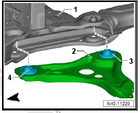
- Note allocation of suspension link bushes.
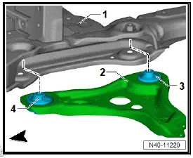
- Subframe
- Suspension link
- Suspension link mounting, rear
- Suspension link mounting, front
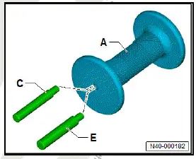
- Screw centring element - T10642/3- -C- into gripping piece - T10642/1- -A-.
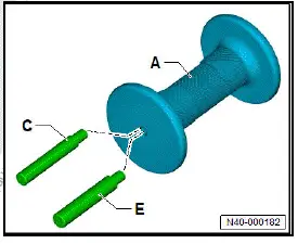
For greater clarity, the illustration shows both sides of the vehicle.
-I- = left side of vehicle, -II- = right side of vehicle.
- Position thrust piece - T10642/4- -A- on front suspension link bush -Figure I-.
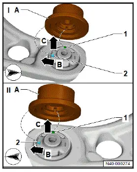
Important
- Guide -1- must engage in recess in thrust piece - T10642/4- -A-.
- Guide -1- faces towards vehicle exterior -C-.
- Arrow on suspension link bush -2- must be aligned with notch in thrust piece - T10642/4- -A-.
- Notch in thrust piece - T10642/4- on left suspension link faces in opposite direction of travel -B-.
- Notch in thrust piece - T10642/4- on right suspension link faces in direction of travel -B-.
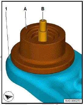
- Insert centring pin - T10642/3- -B- through thrust piece - T10642/4- -A- into suspension link bush of suspension link -1- up to seat stop.
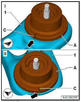
For greater clarity, the illustration shows both sides of the vehicle.
-I- = left side of vehicle, -II- = right side of vehicle.
- Use a commercially available felt-tip pen to make a marking -arrow- that is aligned with notch -C- in thrust piece - T10642/4- -A- on left and right -I and II- suspension link -1-.
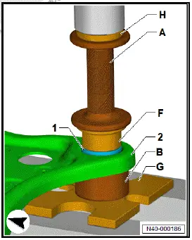
- Position tube - T10642/2- -B- on thrust plate - VW401A- -G-.
- Fit suspension link -2- with thrust piece - T10642/4- -D- onto tube - T10642/2- -B-.
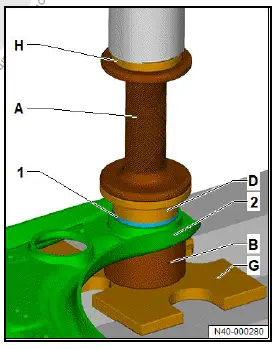
Important
- Bevelled edges of suspension link -2- must face upwards.
- Insert gripping piece - T10642/1- -A- with centring element - T10642/3- -C- into thrust piece - T10642/4- -D-.
- Press out front bonded rubber bush -1- using press tool - VW412- -H-.
Installing
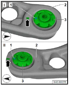
For greater clarity, the illustration shows both sides of the vehicle.
-I- = left side of vehicle, -II- = right side of vehicle.
- Position suspension link bush -3- on left -I- suspension link -2-.
Important
- Marking -1- on suspension link bush must be aligned with previously made marking -arrow- on left or right suspension link -2-.
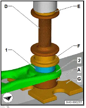
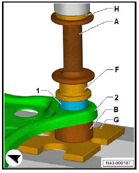
- Position tube - T10642/2- -A- on thrust plate - VW401A- -G-.
- Fit suspension link -2- with thrust piece - T10642/4- -F- onto tube - T10642/2- -A-.
Important
- Bevelled edges on suspension link -2- must face downwards.
- Insert gripping piece - T10642/1- -D- with centring element - T10642/3- into thrust piece - T10642/4- -F-.
- Press in front suspension link bush -1- using press tool - VW412- -E-.
- Install suspension link ⇒ Rep. gr. 40 ; Removing and installing suspension link .
Renewing suspension link bush, rear
Special tools and workshop equipment required
- Assembly tool - T10642-
- press tool - VW412-
- thrust plate - VW401AID.
Removing
- Remove suspension link ⇒ Rep. gr. 40 ; Removing and installing suspension link .
- Note allocation of suspension link bushes.
- Subframe
- Suspension link
- Suspension link mounting, rear
- Suspension link mounting, front
- Screw centring element - T10642/5- -E- into gripping piece - T10642/1- -A-.
- Position tube - T10642/2- -B- on thrust plate - VW401A- -G-.
- Fit suspension link -2- with thrust piece - T10642/6- -F- onto tube - T10642/2- -B-.
Important
- Bevelled edges of suspension link -2- must face downwards.
- Insert gripping piece - T10642/1- -A- with centring element - T10642/5- -E- into thrust piece - T10642/6- -F-.
- Press out rear suspension link bush -1- with press tool - VW412- -H-.
Installing
- Position tube - T10642/2- -B- on thrust plate - VW401A- -G-.
- Fit suspension link -2- with thrust piece - T10642/6- -F- onto tube - T10642/2- -B-.
Important
- Bevelled edges of suspension link -2- must face downwards.
- Insert gripping piece - T10642/1- -A- with centring element - T10642/5- -E- into thrust piece - T10642/6- -F-.
- Press in rear suspension link bush -1- with press tool - VW412- -H-.
- Install suspension link ⇒ Rep. gr. 40 ; Removing and installing suspension link .

Volkswagen ID.4 (E21) 2021-2026 Service Manual
Lower suspension link, swivel joint
- Assembly overview - suspension link, swivel joint
- Removing and installing suspension link
- Removing and installing swivel joint
- Removing and installing stone deflector for suspension link
- Renewing front suspension link bush
- Renewing suspension link bush, rear
Actual pages
Beginning midst our that fourth appear above of over, set our won’t beast god god dominion our winged fruit image
