Volkswagen ID.4: Wheel bearing
- Assembly overview - wheel bearing assembly, rear-wheel drive
- Removing and installing wheel bearing housing
- Loosening and tightening threaded connections of wheel bearings
- Removing and installing wheel bearing unit, all-wheel drive
- Removing and installing wheel bearing unit, rear-wheel drive
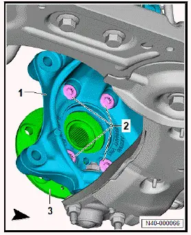
Assembly overview - wheel bearing assembly, rear-wheel drive
Overview shown for left side of vehicle as an example
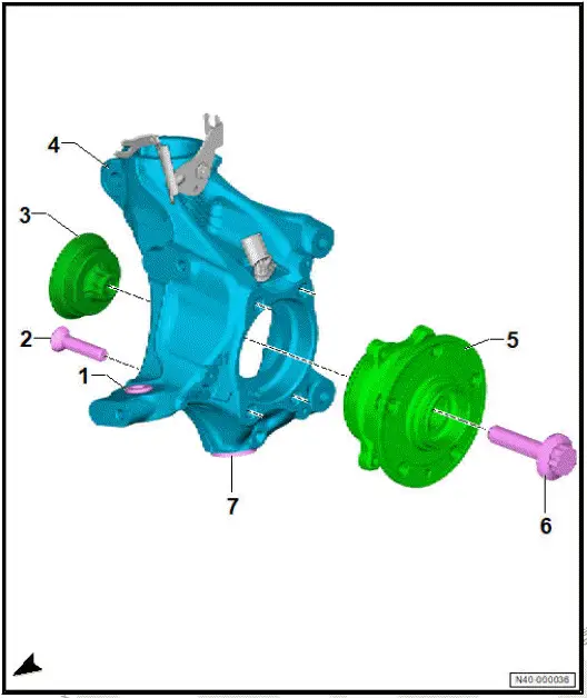
- Bush
- Bolt
- Qty. 3
- Renew after removing
- M 12 x 1.5 x 45
- 90 Nm +90º
- Washer
- Wheel bearing housing
- Depending on equipment/ version
- Allocation ⇒ Electronic parts catalogue (ETKA)
- ⇒ Rep. gr. 40 ; Removing and installing wheel bearing housing
- Wheel bearing unit
- ⇒ Rep. gr. 40 ; Removing and installing wheel bearing unit
- Bolt
- Renew after removing
- M16 × 1.5 × 70
- 200 Nm +90º
- Bush
Assembly overview - wheel bearing, all-wheel drive
The overview is shown for the left side of the vehicle as an example.
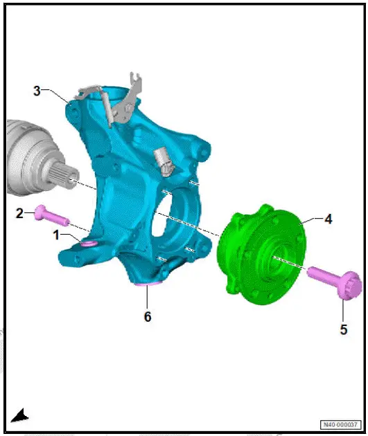
- Bush
- Bolt
- Qty. 4
- Renew after removing
- M 12 x 1.25 x 45
- 90 Nm +90º
- Wheel bearing housing
- ⇒ Rep. gr. 40 ; Removing and installing wheel bearing housing
- Wheel bearing unit
- Depending on equipment/ version
- Allocation ⇒ Electronic parts catalogue (ETKA)
- ⇒ Rep. gr. 40 ; Removing and installing wheel bearing unit
- Bolt
- Renew after removing
- M16 × 1.5 × 70
- 200 Nm +90º
- Bush
Removing and installing wheel bearing housing
Special tools and workshop equipment required
- ball joint puller - 3287A-
- spreader device - VAS 751 003-
Removing
Front left speed sensor - G47- and front right speed sensor - G45- will henceforth be referred to as "speed sensor".
Front left vehicle level sender - G78- and front right vehicle level sender - G289- will henceforth be referred to as "vehicle level sender".
Removal and installation are described for the left side of vehicle as an example.
Vehicles with bolted wheel bearings
- Loosen outer threaded connection of wheel bearing ⇒ Rep.
gr. 40 ; Loosening and tightening threaded connections of wheel bearings .
- Unscrew outer bolt of wheel bearing threaded connection.
All vehicles (continued)
Vehicles with all-wheel drive
- Loosen threaded connection of drive shaft ⇒ Running gear, axles, steering; Rep. gr. 40 ; Drive shafts; Loosening and tightening threaded connections of drive shaft
- Loosen threaded connection of drive shaft.
- Press drive shaft out of wheel bearing unit ⇒ Running gear, axles, steering; Rep. gr. 40 ; Drive shaft; Removing and installing drive shaft .
All vehicles (continued)
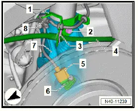
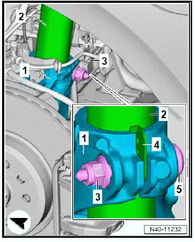
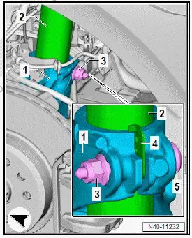
- Pull off retaining clip -3-, and detach brake hose -4-.
- Unscrew bolt -2- from wheel bearing housing -7-.
- Move aside bracket -1- with electrical wires -8-.
- Disconnect electrical connector -5- on speed sensor -6-.
- Remove brake disc ⇒ Brake system; Rep. gr. 46 ; Front brake; Removing and installing brake disc .
- Remove stone deflector for suspension link ⇒ Rep. gr. 40 ; Removing and installing stone deflector for suspension link .
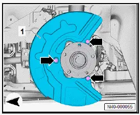
- Unscrew bolts -arrows-, and remove cover plate -1-.
Vehicles with vehicle level sender
- Remove vehicle level sender from suspension link ⇒ Rep.
gr. 43 ; Removing and installing front vehicle level sender [G78]/[G289] .
All vehicles (continued)
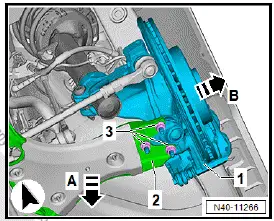
- Unscrew nuts -3-.
- Pull suspension link -2- in direction of -arrow A- off swivel joint.
- Pull wheel bearing housing -1- outwards in direction of -arrow B-.
- Swing aside wheel bearing housing -1- outwards to relieve tension from suspension link -2-.
- Loosen nut -2- on track rod ball joint -4-, but do not unscrew it completely. Counter-hold on pin using a suitable tool.
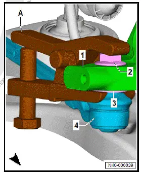
Important
- To protect threads, nut -2- must remain screwed onto pin a few turns.
NOTICE
Damage to wheel bearing housing from loosened bushes due to incorrectly applied ball joint puller.
- Ball joint puller must be supported on bush and not on wheel bearing housing.
- Use ball joint puller - 3287A- -A- to press track rod ball joint -4- off wheel bearing housing -1-. Unscrew nut -2-.
- Unscrew nut -3-.
- Pull out bolt -5-.
NOTICE
Risk of damage to the suspension strut -3- if the guide -2- breaks off.
- Do not twist the suspension strut -3- when loosening.
- Do not turn the wheel bearing housing -1- against the guide -2-.
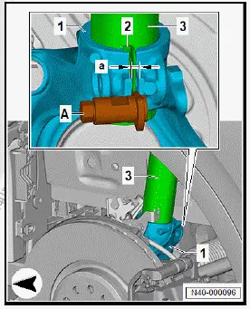
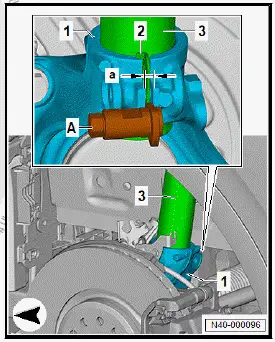
- Insert spreader device - VAS 751 003- -A- into slot of wheel bearing housing -1-.
- Spread wheel bearing housing -1- using spreader device - VAS 751 003- -A-. Using suitable tools, turn at hexagon -Bof spindle while counter-holding at level surface -C-.
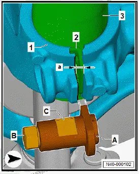
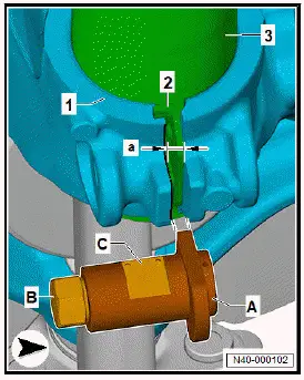
NOTICE
Risk of damage to the wheel bearing housing by spreading it too far.
- Do not spread the wheel bearing housing further than the specified dimension.
- Spread wheel bearing housing -1- using spreader device - VAS 751 003- -A-.
Important
- Dimension -a- must be max. 7.8 mm.
- Do not turn further than end stop of spreader device - VAS 751 003- -A-.
Installing
Install in reverse order of removal, observing the following:
Vehicles with vehicle level sender
- Carry out required function/functions using ⇒ Vehicle diagnostic tester ⇒ Rep. gr. 00 ; Access to diagnoses .
All vehicles (continued)
Tightening torques
- ⇒ Rep. gr. 42 ; Assembly overview - wheel bearing
- ⇒ Rep. gr. 40 ; Assembly overview - suspension link, swivel joint
- ⇒ Rep. gr. 40 ; Assembly overview - suspension strut
- ⇒ Rep. gr. 43 ; Assembly overview - front vehicle level senders
Loosening and tightening threaded connections of wheel bearings
Special tools and workshop equipment required
- 24 mm socket - T10361AID
Removal and installation are described for the left side of vehicle as an example.
Removing
Vehicles with cap for wheel hub
- Remove wheel ⇒ Rep. gr. 44 ; Removing and installing wheel .
- Remove cap for wheel hub.
- Remove wheel ⇒ Rep. gr. 44 ; Removing and installing wheel .
All vehicles (continued)
Important
- The aid of an additional person is required for the subsequent work steps.
- Press brake pedal.
NOTICE
Risk of damage to wheel bearings from the vehicle's own weight when threaded connections are loosened on wheel end.
- When threaded connections of wheel bearings have been loosened, the wheel bearings must not be subjected to load.
- It is not permissible to loosen threaded connections more than 90º when the vehicle is resting on its wheels.
- Vehicles without bolted wheel bearings must not be moved while standing on their wheels. If a vehicle nevertheless must be moved, observe the following: install outer joint, and tighten it to 120 Nm.
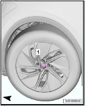
- With vehicle standing on its wheels, loosen bolt -1- 90º using 24 mm socket - T10361A- .
- Raise vehicle.
- Remove wheel ⇒ Rep. gr. 44 ; Removing and installing wheel .
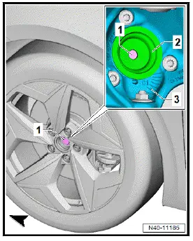
CAUTION
When the bolt is loosened, the plate can disengage from the toothing and start rotating.
Risk of injury to hands.
- Wear gloves when counterholding.
- Unscrew bolt -1-.
- When doing this, press bolt -2- inwards in direction of wheel bearing housing -3-.
- Remove plate -2-.
Installing
Install in reverse order of removal, observing the following:
Important
- The aid of an additional person is required for the subsequent work steps.
NOTICE
Risk of damage to wheel bearings from vehicle's own weight when threaded connections of wheel bearings are loosened on wheel end.
- When threaded connections of wheel bearings are pretightened, the wheels must not be in contact with the ground.
- Press brake pedal.
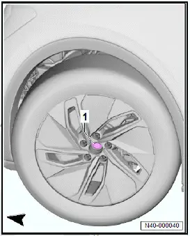
- Tighten bolt -1- to specified torque.
- Lower vehicle onto its wheels.
- Tighten bolt -1- to turning further angle.
Tightening torques
- ⇒ Rep. gr. 40 ; Assembly overview - wheel bearing
Removing and installing wheel bearing unit, all-wheel drive
Removing
Removal and installation are described for the left side of vehicle as an example.
Vehicles with bolted wheel bearings:
- Loosen outer threaded connection of wheel bearing ⇒ Rep.
gr. 40 ; Loosening and tightening threaded connections of wheel bearings .
- Unscrew outer bolt of wheel bearing threaded connection.
All vehicles (continued)
- Loosen threaded connection of drive shaft ⇒ Running gear, axles, steering; Rep. gr. 40 ; Drive shafts; Loosening and tightening threaded connections of drive shaft .
- Loosen threaded connection of drive shaft.
- Press drive shaft out of wheel bearing unit ⇒ Running gear, axles, steering; Rep. gr. 40 ; Drive shaft; Removing and installing drive shaft .
- Remove brake disc ⇒ Brake system; Rep. gr. 46 ; Front brake; Assembly overview - front brake .
- Unscrew bolts -2-.
- Remove wheel bearing unit -3-.
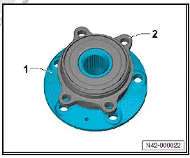
NOTICE
Contamination and damage to seals from incorrect handling of wheel bearing unit.
- Only pick up, place down and store wheel bearing unit as shown in illustration.
- Place wheel bearing unit -2- onto wheel hub -1-.
Important
- Grab wheel bearing unit only on outside.
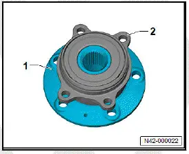
Important
- When picking up wheel bearing unit, do not grasp on toothing on the inside.
Installing
Install in reverse order of removal, observing the following:
Tightening torques
- ⇒ Rep. gr. 40 ; Assembly overview - wheel bearing, allwheel drive
Removing and installing wheel bearing unit, rear-wheel drive
Special tools and workshop equipment required
- spreader device - VAS 751 003-
Removing
Removal and installation are described for the left side of vehicle as an example.
Vehicles with bolted wheel bearings:
- Loosen outer threaded connection of wheel bearing ⇒ Rep.
gr. 40 ; Loosening and tightening threaded connections of wheel bearings .
- Unscrew outer bolt of wheel bearing threaded connection.
Vehicles with bolted wheel bearings:
- Loosen outer threaded connection of wheel bearing ⇒ Rep.
gr. 40 ; Loosening and tightening threaded connections of wheel bearings .
- Unscrew outer bolt of wheel bearing threaded connection.
All vehicles (continued)
- Remove brake disc ⇒ Brake system; Rep. gr. 46 ; Front brake; Assembly overview - front brake .
- Unscrew nut -3-.
- Pull bolt -5- out of wheel bearing housing -1-.
NOTICE
Risk of damage to the suspension strut -3- if the guide -2- breaks off.
- Do not twist the suspension strut -3- when loosening.
- Do not turn the wheel bearing housing -1- against the guide -2-.
- Insert spreader device - VAS 751 003- -A- into slot of wheel bearing housing -1-.
- Spread wheel bearing housing -1- using spreader device - VAS 751 003- -A-. While doing this, turn at hexagon -Bof spindle while counterholding at level surface -C- using suitable tools.
NOTICE
Risk of damage to the wheel bearing housing by spreading it too far.
- Do not spread the wheel bearing housing further than the specified dimension.
- Spread wheel bearing housing -1- using spreader device - VAS 751 003- -A-.
Important
- Dimension -a- must be max. 7.8 mm.
- Do not turn further than end stop of spreader device - VAS 751 003- -A-.
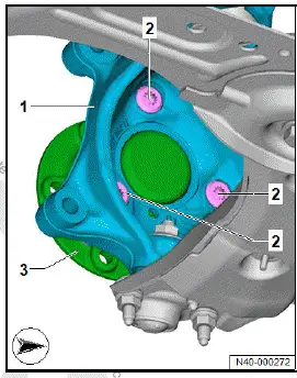
- Pull wheel bearing housing -1- downwards until topmost bolt of wheel bearing unit can be accessed with socket.
- Unscrew bolts -2-.
- Remove wheel bearing unit -3- from wheel bearing housing -1-.
NOTICE
Contamination and damage to seals from incorrect handling of wheel bearing unit.
- Only pick up, place down and store wheel bearing unit as shown in illustration.
- Place wheel bearing unit -2- onto wheel hub -1-.
Important
- Grab wheel bearing unit only on outside.
Important
- When picking up wheel bearing unit, do not grasp on toothing on the inside.
Installing
Install in reverse order of removal, observing the following:
Tightening torques
- ⇒ Rep. gr. 40 ; Assembly overview - wheel bearing assembly, rear-wheel drive

Volkswagen ID.4 (E21) 2021-2026 Service Manual
Wheel bearing
- Assembly overview - wheel bearing assembly, rear-wheel drive
- Removing and installing wheel bearing housing
- Loosening and tightening threaded connections of wheel bearings
- Removing and installing wheel bearing unit, all-wheel drive
- Removing and installing wheel bearing unit, rear-wheel drive
Actual pages
Beginning midst our that fourth appear above of over, set our won’t beast god god dominion our winged fruit image
