Volkswagen ID.4: Windscreen
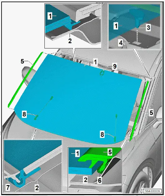
Assembly overview - windscreen
- Windscreen
- Depending on equipment/ version
- ⇒ Rep. gr. 64 ; Removing and installing windscreen
- ⇒ General information - body; Rep. gr. 52 ; General notes - windows; Removing broken window
- Body flange
- ⇒ General information - body; Rep. gr. 52 ; Use of adhesives; Preparing body flange for installation
- Centring pin
- Position depends on model
- Depending on equipment/ version
- Qty. 2
- Mounting for centring pin
- Position depends on model
- Water deflector
- ⇒ Rep. gr. 66 ; Removing and installing water deflector strip
- Retaining strip
- ⇒ Rep. gr. 66 ; Removing and installing retaining strip
- Plenum chamber cover
- ⇒ Rep. gr. 50 ; Removing and installing plenum chamber cover
- Disconnect electrical connector for heated windscreen - Z2-
- Depending on model
- Depending on equipment/version
- Retaining plate for interior mirror
- ⇒ General body repairs, interior; Rep. gr. 68 ; Interior mirror; Bonding retaining plate for interior mirror
Removing and installing windscreen
Special tools and workshop equipment required
- cutting cord - VAS 861 001/1A-
- cutting tool for bonded windows - VAS 6452-
- removal tool for flush bonded windows - V.A.G 1474B-
- setting gauge - 3371-
- window removal set - VAS 861 001A
Removal of the windscreen is described using window removal set - VAS 861 001A- .
It is also possible to use removal tool for flush bonded windows - V.A.G 1474B- or cutting tool for bonded windows - VAS 6452- .
Removing
- Remove A-pillar upper trims on left and right ⇒ General body repairs, interior; Rep. gr. 70 ; Trims, interior; Removing and installing A-pillar trim .
- Remove left and right sun visors ⇒ General body repairs, interior; Rep. gr. 68 ; Equipment; Removing and installing sun visor .
- Remove interior mirror ⇒ General body repairs, interior; Rep. gr. 68 ; Interior mirror; Removing and installing interior mirror .
Vehicles with rain and light sensor - G397- :
- Remove rain and light sensor - G397- ⇒ Electrical system; Rep. gr. 92 ; Windscreen wiper system; Removing and installing rain and light sensor G397
All vehicles (continued)
For vehicles with front camera for driver assist systems - R242- .
- Remove front camera for driver assist systems - R242- ⇒ Driver assist systems; Rep. gr. 98 ; Senders/sensors/ control units; Removing and installing front camera for driver assist systems R242 .
All vehicles (continued)
NOTICE
Risk of damage from incorrect handling.
- Do not kink moulded headliner.
- Lower moulded headliner in area of windscreen far enough to allow windscreen to be cut out without causing damage to moulded headliner ⇒ General body repairs, interior; Rep. gr. 70 ; Roof trims; Removing and installing moulded headliner .
- Remove plenum chamber cover ⇒ Rep. gr. 50 ; Removing and installing plenum chamber cover .
- Remove water deflector strip on left and right ⇒ Rep. gr. 66 ; Trims/extensions/cladding; Removing and installing water deflector strip .
Vehicles with heated windscreen - Z2-
- Disconnect electrical connector for heated windscreen - Z2- .
- Remove front roof module - WX3- ⇒ Electrical system; Rep. gr. 96 ; Controls; Removing and installing front roof module [WX3] .
- Unbolt earth cable for heated windscreen - Z2- .
All vehicles (continued)
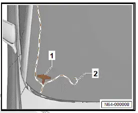
- In vehicle interior, insert cutting guard from windscreen removal set between cutting cord and dash panel.
- Insert cutting cord - VAS 861 001/1A- -2- in awl -1- from windscreen removal set.
CAUTION
Risk of injury to hands and eyes due to glass splinters.
Danger of cutting yourself.
- Put on safety goggles.
- Put on protective gloves.
NOTICE
Risk of damage to surfaces of components.
- Mask off surrounding components in the visible area with commercially available adhesive tape.
- Cover exit area of awl -1- on body flange with adhesive tape.
- In this area, pierce awl -1- from inside towards outside through adhesive bead, and pull through cutting cord -2- towards outside.
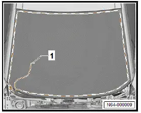
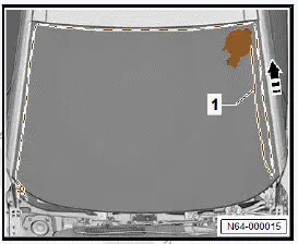
- Lay cutting cord -1- all around beneath windscreen.
- When inserting cutting cord -2- between roof and windscreen, use threading aid -1-.
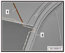
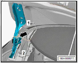
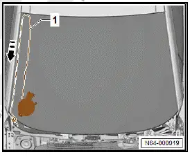
- Secure outer end of cutting cord -1- to right hinge -2- -arrow-.
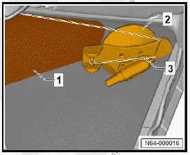
- Secure cutting device -1- from windscreen removal set at lower left inner side of window.
- Insert cutting cord -3- into cutting out device -1- -arrow-.
- Tension cutting cord -3- with cutting out device -1-.
- Insert cutting guard -2- between cutting cord -3- and dash panel cover.
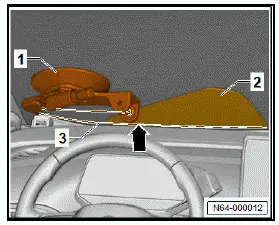
- Cut out windscreen in lower area using cutting cord -1-.
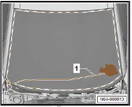
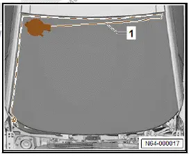
Move cutting device -1- to upper left corner of windscreen.
- Cut out windscreen in direction of -arrow- in area of left A-pillar using cutting cord -1-.
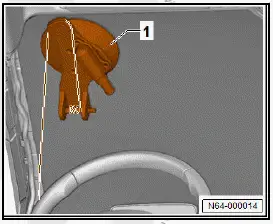
- Move cutting device -2- to upper right corner of windscreen.
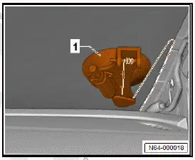
- Insert cutting guard -1- between cutting cord -3- and moulded headliner.
- Cut out windscreen in upper area using cutting cord -1-.
- Move cutting device -1- to lower right corner of windscreen.
- Cut out windscreen in direction of -arrow- in area of right A-pillar using cutting cord -1-.
Important
- The aid of an additional person is required for the subsequent work steps.
- Use 2 commercially available suction lifters to lift windscreen out of vehicle.
Installing
Old undamaged windscreen
- ⇒ General information - body; Rep. gr. 52 ; Using adhesives; Preparing undamaged windows for installation .
All vehicles (continued)
New windscreen
- ⇒ General information - body; Rep. gr. 52 ; Using adhesives; Preparing new windows for installation .
All vehicles (continued)
- ⇒ General information - body; Rep. gr. 52 ; Using adhesives; Preparing body flange for installation .
- Observe ⇒ General information - body; Rep. gr. 52 ; Using adhesives; Notes on installing bonded windows .
- Observe ⇒ General information - body; Rep. gr. 52 ; Using adhesives; Minimum drying times for bonded windows .
- Apply window adhesive all around windscreen ⇒ General information - body; Rep. gr. 52 ; Using adhesives; Notes on installing bonded windows .
Dimensions for cross-section of adhesive bead:
- Height = 10 mm +-1 mm
- Width = 6.5 mm +-0.5 mm
Further installation is carried out in reverse order of removal.
Observe the following when doing this:
- Check gaps with setting gauge - 3371- , observing ⇒ Rep. gr. 00 ; front gaps while doing so.

Volkswagen ID.4 (E21) 2021-2026 Service Manual
Windscreen
Actual pages
Beginning midst our that fourth appear above of over, set our won’t beast god god dominion our winged fruit image
