Volkswagen ID.4: Electric drive motor
Calibrating three-phase current drive VX54
Calibration of the three-phase current drive - VX54- becomes necessary if:
- the event memory of systems relevant to OBD has been cleared;
- the software for the electric drive control unit - J841- was updated;
- the electric drive control unit - J841- has been renewed;
- the power and control electronics for electric drive - JX1- has been renewed;
- the three-phase current drive - VX54- has been renewed.
Calibration is preformed automatically the first time the vehicle is driven. The power output of the drive motor is restricted until the motor has been successfully calibrated.
If the calibration is to be carried out manually:
- Carry out function "Calibrate electric drive motor" using ⇒ Vehicle diagnostic tester ⇒ Rep. gr. 00 ; Access to diagnoses .
- Leakage test of electric drive motor, rear
- Assembly overview - electric drive motor, rear
- Assembly overview - electric drive motor, front
- Removing and installing drive motor rotor position sender 1 [G713]
- Removing and installing drive motor rotor position sender, front
Leakage test of electric drive motor, rear
Special tools and workshop equipment required
- Leakage test kit - VAS 691 005/15-
- distributing mechanism - VAS 691 005/1-
- plug - T10607/4-
- plug - T10633-
- pressure and vacuum pump - VAS 671 005-
- pressure sensor - V.A.G 1397B-
- seal - T10634-
- stopper - VAS 691 005/11-2-
- test adapter - VAS 691 005/4-
The power and control electronics for electric drive - JX1- will henceforth be referred to as "power electronics".
Important
- Three-phase current drive - VX54- with power and control electronics for electric drive - JX1- must be secured to motor and gearbox support.
- Sealant must be allowed to dry for at least 15 minutes before carrying out the leakage test.
Carry out the steps below one after the other.
Step 1: Leak testing of tools
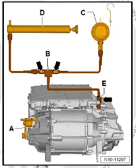
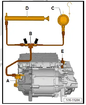
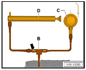
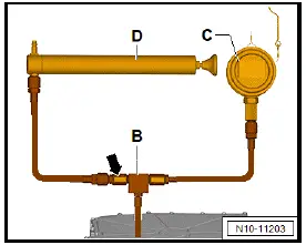
- Connect pressure and vacuum pump - VAS 671 005- -D- on pressure side to distributing mechanism - VAS 691 005/1- -B-.
- Connect pressure sensor - V.A.G 1397B- -C- to distributing mechanism -B-.
- Open all shut-off taps -arrows- on distributing mechanism -B-.
- Connect distributing mechanism -B- to adapter - VAS 691 005/15-3- -E-.
- Switch on pressure sensor -C-. Select "mbar" and relative pressure measurement "rEL".
- Close shut-off tap -arrow- on adapter -E-.
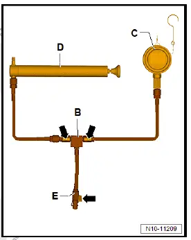
- Generate a pressure of 1000 mbar using pressure and vacuum pump -D-.
- When pressure is reached, close shut-off tap -arrow- on distributing mechanism -B-.
- Observe pressure sensor -C- for approx. 1 minute.
Important
- The pressure must not drop.
Note
Due to the pressure sensor's high accuracy, the displayed pressure may fluctuate.
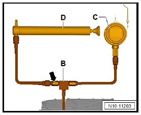
Step 2: Leak testing of motor and gearbox
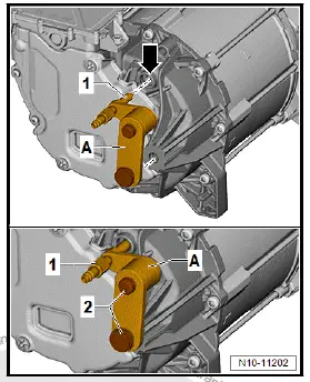
- Seal electrical connections of power electronics -1- with plug - T10607/4- -J- and plug - T10633- -K-.
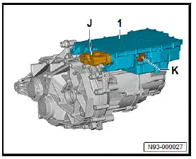
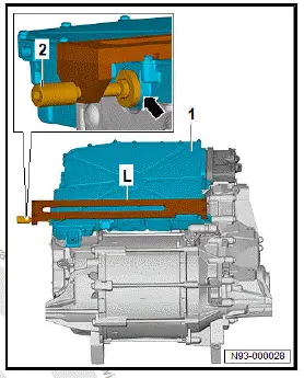
- Fit seal - T10634- -L- onto power and control electronics -1- as shown in illustration.
- Position sealing disc centrally in front of bleeder valve -arrow-.
- Screw in spindle -2- by hand.
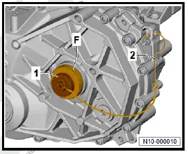
- Insert stopper - VAS 691 005/15-1- -F- in left input shaft flange.
- Screw in clamping nut -1- by hand.
- Hook safety cable -2- onto motor.
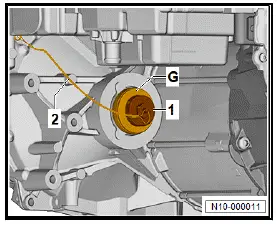
- Insert stopper - VAS 691 005/15-1- -G- in right input shaft flange.
- Screw in clamping nut -1- by hand.
- Hook safety cable -2- onto motor.
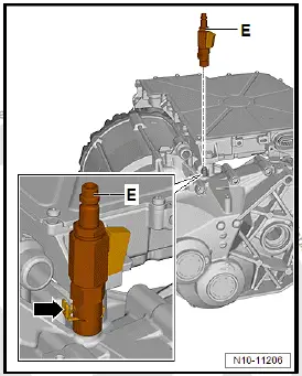
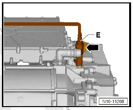
- Press in locking element -arrow- and fit adapter - VAS 691 005/15-3- -E- onto gearbox breather.
- Release locking element -arrow- and pull to check it has locked.
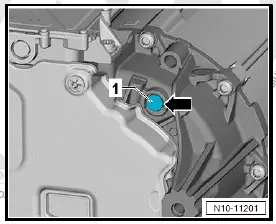
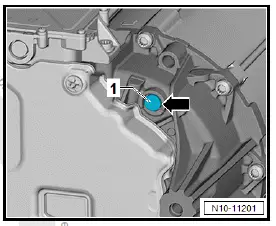
- Using a small screwdriver, carefully lever out bleeder valve -1- -arrow-.
- Mount test adapter - VAS 691 005/15-2- -A- on motor.
Important
- Compressed air connection -1- must align with hole for bleeder valve -arrow-.
- Screw in knurled screws -2- by hand.
- Turn compressed air connection -1- centrally against hole for bleeder valve until it is finger-tight.
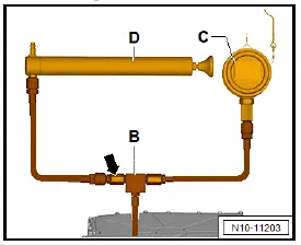
- Connect distributing mechanism -B- with pressure sensor -C- and pressure and vacuum pump -D- to adapter -E-.
- Open all shut-off taps -arrows-.
- Switch on pressure sensor -C-. Select "mbar" and relative pressure measurement "rEL".
- Generate a pressure of 200 mbar using pressure and vacuum pump -D-.
- When pressure is reached, close shut-off tap -arrow- on distributing mechanism -B-.
- Observe pressure sensor for 5 minutes.
Important
- The pressure must not drop by more than 2 mbar.
- If the pressure drops by more than 2 mbar locate the leak using a commercially available leak detection spray.
- If gearbox side is leak-tight, close shut-off tap -arrow- on adapter -E-.
Note
Pressure in gearbox must not be released. It is needed to leaktest the motor side.
Checking motor side for leaks
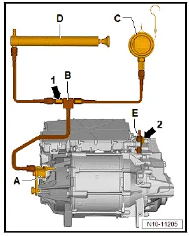
- Connect distributing mechanism -B- with pressure sensor -C- and pressure and vacuum pump -D- to test adapter - VAS 691 005/15-2- -A-.
- Open all shut-off taps -arrows- on distributing mechanism -B-.
- Switch on pressure sensor -C-. Select "mbar" and relative pressure measurement "rEL".
- Generate a pressure of 200 mbar using pressure and vacuum pump -D-.
- When pressure is reached, close shut-off tap -arrow- on distributing mechanism -B-.
- Observe pressure sensor -C- for 5 minutes.
Important
- The pressure must not drop by more than 2 mbar.
- If the pressure drops by more than 2 mbar locate the leak using a commercially available leak detection spray.
- Following leakage test, remove pressure and vacuum pump -D-.
- First release pressure on motor side by opening shut-off tap -arrow 1-. Then open shut-off tap -arrow 2-.
- Remove all tools.
- Apply thin coat of special lubricant to sealing seat for bleeder valve on bearing plate -arrow-, and install new bleeder valve -1-.
Special lubricant ⇒ Electronic parts catalogue (ETKA)
Step 3: Leak testing motor on coolant side
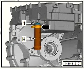
- Seal coolant connection -1- at bottom on power electronics using stopper - VAS 691 005/11-2- -H-.
- Secure stopper with hose clip -arrow-.
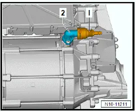
- Connect test adapter - VAS 691 005/4- -I- to coolant connection -2-.
- Connect distributing mechanism -B- with pressure sensor -C- and pressure and vacuum pump -D- to test adapter -I-.
- Open all shut-off taps -arrows- on distributing mechanism -B-.
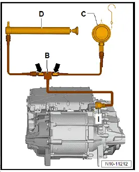
- Generate a pressure of 1000 mbar using pressure and vacuum pump -D-.
- When this pressure has been reached, close shut-off tap -arrow-.
- Observe pressure sensor -C- for 5 minutes.
Important
- The pressure must not drop by more than 1 mbar.
- If the pressure drops by more than 1 mbar locate the leak using a commercially available leak detection spray.
Important
- If leaks have been located and sealed, repeat leakage test.
- If no leakage was detected, remove all tools.
Assembly overview - electric drive motor, rear
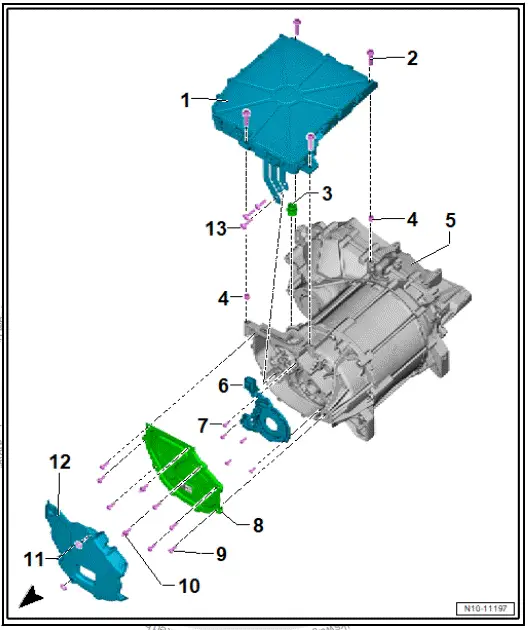
- Power and control electronics for electric drive - JX1-
- With electric drive control unit - J841-
- With intermediate circuit capacitor 1 - C25-
- With DC/AC converter for drive motor - A37-
- ⇒ Rep. gr. 93 ; Removing and installing power and control electronics for electric drive at rear
- Bolt
- Qty. 4
- Renew after removing
- 16 Nm +135º
- Connecting piece
- Renew after removing
- Dowel sleeve
- Qty. 2
- Three-phase current drive - VX54- with gearbox
- With electric drive motor - V141-
- ⇒ Rep. gr. 10 ; Removing rear motor
- Drive motor rotor position sender 1 - G713-
- With drive motor temperature sender - G712-
- ⇒ Rep. gr. 93 ; Removing and installing drive motor rotor position sender 1 [G713]
- Bolt
- Qty. 6
- Renew after removing
- 4 Nm +90º
- Cover
- Renew after removing
- Bolt
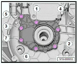
- Qty. 7
- Renew after removing
- Specified torque and tightening sequence
- Centre hex stud
- Qty. 2
- Renew after removing
- Specified torque and tightening sequence
- Clamping washer
- Qty. 2
- Noise insulation
- Bolt
- Qty. 3
- Renew after removing
- 8 Nm +90º
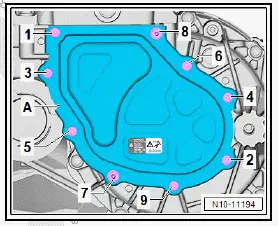
Cover - specified torque and tightening sequence
Assembly overview - electric drive motor, front
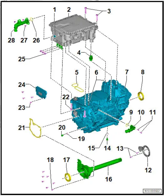
- Bleeder valve
- Power and control electronics 2 for electric drive - JX4-
- With electric drive control unit 2 - J944-
- With intermediate circuit capacitor 2 - C26-
- With DC/AC converter for drive motor 2 - A55-
- ⇒ Rep. gr. 93 ; Removing and installing power and control electronics for electric drive, front
- Bolt
- Qty. 2
- Renew after removing
- 30 Nm +45º
- Connecting piece
- Renew after removing
- Gasket/sealant
- Gasket or sealant, depending on equipment
- Renew after removing
- Dowel pins
- Qty. 2
- Renew after removing
- Three-phase current drive 2 - VX97- with gearbox
- With electric drive motor 2 - V717-
- Seal
- O-ring
- Renew after removing
- Coolant connection
- Bolt
- Qty. 2
- Renew after removing
- 5 Nm
- Rotor position sender 1 for drive motor 2 - G1147-
- With drive motor 2 temperature sender - G1146-
- ⇒ Rep. gr. 93 ; Removing and installing drive motor rotor position sender, front
- Bolt
- Qty. 2
- 3.5 Nm
- Oil drain plug
- Renew after removing
- 15 Nm
- Seal
- Renew after removing
- Bearing plate with shaft
- Seal
- Bolt
- Qty. 7
- Renew after removing
- Specified torque and tightening sequence
- Seal
- Plug
- Renew after removing
- 15 Nm
- Gasket
- Renew after removing
- Bolt
- Qty. 2
- Renew after removing
- 30 Nm +45º
- Bolt
- Tighten diagonally and alternately
- Qty. 4
- Renew after removing
- 6 Nm
- Cover
- Renew after removing
- Bolt for bus bar
- Qty. 3
- Renew after removing
- 9 Nm
- O-ring
- Renew after removing
- Bolt
- Qty. 2
- Renew after removing
- 5 Nm
- Coolant connection
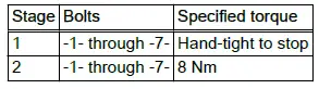
Bearing plate - specified torque and tightening sequence
Removing and installing drive motor rotor position sender 1 [G713]
Drive motor rotor position sender 1 - G713- will be referred to hereafter as "sender".
Note
Bolts could fall into the motor. Turn the motor to horizontal position.
Removing
- Remove power and control electronics for electric drive - JX1- ⇒ Rep. gr. 93 ; Removing and installing power and control electronics for electric drive .
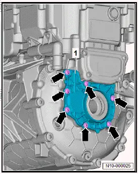
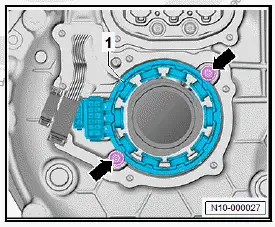
- Unscrew bolts -arrows- for sender -A-.
![Volkswagen ID.4. Removing and installing drive motor rotor position sender 1 [G713]](images/manuals/353/volkswagen_id_4_removing_and_installing_drive_motor_rotor_position_2312.webp)
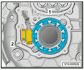
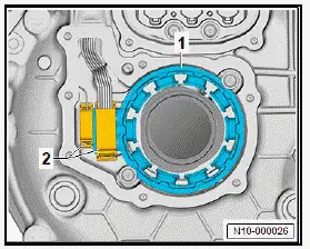
- Pull sender -A- off connection -2- -arrow-.
![Volkswagen ID.4. Removing and installing drive motor rotor position sender 1 [G713]](images/manuals/353/volkswagen_id_4_removing_and_installing_drive_motor_rotor_position_2313.webp)
Installing
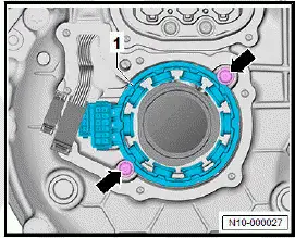
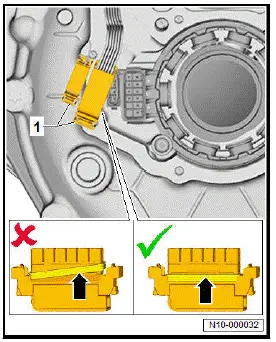
- Fit sender -A- onto connection -2- -arrow-.
![Volkswagen ID.4. Removing and installing drive motor rotor position sender 1 [G713]](images/manuals/353/volkswagen_id_4_removing_and_installing_drive_motor_rotor_position_2314.webp)
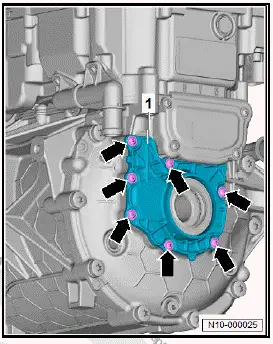
- Make sure that sender -A- is properly seated on dowel pin -arrow-.
- Insert bolts -1- and -2-.
- First tighten bolts -1- and then bolts -2-.
![Volkswagen ID.4. Removing and installing drive motor rotor position sender 1 [G713]](images/manuals/353/volkswagen_id_4_removing_and_installing_drive_motor_rotor_position_2315.webp)
- Install power and control electronics for electric drive - JX1- ⇒ Rep. gr. 93 ; Removing and installing power and control electronics for electric drive, rear .
Tightening torques
- ⇒ Rep. gr. 93 ; Assembly overview - power and control electronics for electric drive, rear
Removing and installing drive motor rotor position sender, front
Rotor position sender 1 of drive motor 2 - G1147- will be referred to hereafter as "sender".
Removing
- ⇒ Rep. gr. 10 ; Remove front motor .
- ⇒ Rep. gr. 10 ; Secure motor to engine and gearbox support .
- Unscrew bolts -arrows- for bearing plate -1-.
- Pull bearing plate together with shaft out of motor.
- Pull electrical connectors -2- off sender -1-.
- Unscrew bolts -arrows-, and detach sender -1-.
Installing
- Insert sender -1-, and tighten bolts -arrows-.
- Make sure that gasket -arrow- has been properly inserted at electrical connector.
- Connect electrical connectors -2-. Check for proper engagement by pulling.
- Thoroughly clean sealing surfaces on bearing plate and motor.
- Insert bearing plate with shaft and new seal into motor.
- Tighten bolts -arrows- for bearing plate.
Tightening torques
- ⇒ Rep. gr. 93 ; Assembly overview - electric drive motor, front

Volkswagen ID.4 (E21) 2021-2026 Service Manual
Electric drive motor
- Leakage test of electric drive motor, rear
- Assembly overview - electric drive motor, rear
- Assembly overview - electric drive motor, front
- Removing and installing drive motor rotor position sender 1 [G713]
- Removing and installing drive motor rotor position sender, front
Actual pages
Beginning midst our that fourth appear above of over, set our won’t beast god god dominion our winged fruit image
