Volkswagen ID.4: Mouldings, trims, extensions
- Assembly overview - covers
- Assembly overview - side member trim
- Assembly overview - C-pillar trim
- Removing and installing step moulding
- Removing and installing side member trim
- Removing and installing retaining strip
- Removing and installing A-pillar cover
- Removing and installing B-pillar trim on door
- Removing and installing trim panel for C-pillar
- Removing and installing front wheel arch cover
- Removing and installing wing cover
- Removing and installing rear wheel arch cover
- Removing and installing trim cover for front door
- Removing and installing trim cover for rear door
- Removing and installing trim cover for rear door, GTX
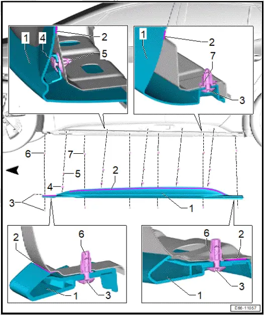
Assembly overview - covers
Overview is shown for left side of vehicle as an example
- Front door moulding
- Renew after removing
- ⇒ "3.18 Removing and installing trim cover for front door"
- Bonding surface
- Adhesive tape
- Clip
- Qty. 3
- Centring pin
- Qty. 2
- Trim cover for rear door
- Renew after removing
- ⇒ Rep. gr. 66 ; Removing and installing trim cover for rear door
- Clip
- Qty. 5
- Centring pin
- Qty. 3
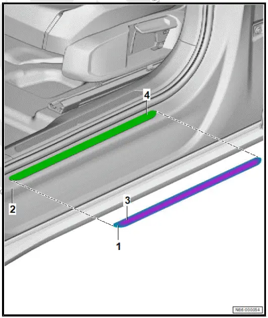
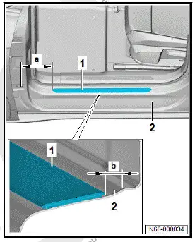
Assembly overview - step moulding
Overview is shown for left side of vehicle as an example
- Step moulding
- Renew after removing
- ⇒ Rep. gr. 66 ; Removing and installing step moulding
- Outer side member
- Double-sided adhesive tape
- Bonding surface
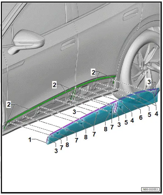
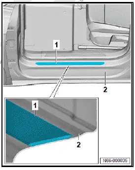
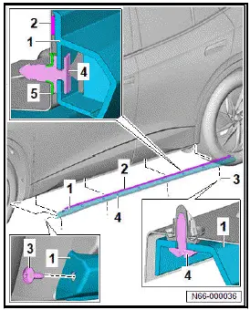
Assembly overview - side member trim
The assembly overview here applies to the left side of the vehicle.
- Side member trim
- Renew after removing
- ⇒ Rep. gr. 66 ; Removing and installing side member trim
- Adhesive tape
- Bolt
- 7x
- 2 Nm
- Clip
- 5x
- Grommet
- Depending on equipment/ vehicle version
- 5x
- Expanding nut
- At front and rear.
- 2x
- Expanding nut
- 4x
Assembly overview - water deflector strip
Overview is shown for right side of vehicle as an example
- Water deflector
- ⇒ Rep. gr. 66 ; Removing and installing water deflector strip
- A-pillar
- Pop rivet
- Quantity and position depending on model
- Qty. 5 or 6
- Retaining strip
- ⇒ Rep. gr. 66 ; Removing and installing retaining strip
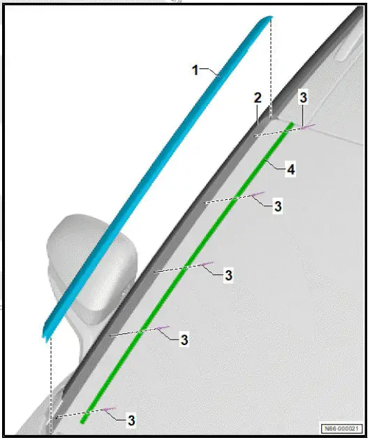
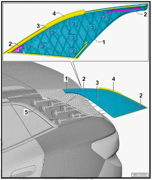
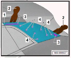
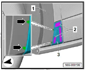
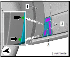
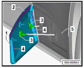
Assembly overview - C-pillar trim
The overview is shown for the left side of the vehicle as an example.
- C-pillar trim
- Renew after removing
- ⇒ Rep. gr. 66 ; Removing and installing trim panel for C-pillar
- Adhesive tape
- Can only be renewed along with C-pillar trim
- Clip
- Can only be renewed along with C-pillar trim
- Qty. 8
- Seal
- Can only be renewed along with C-pillar trim
- C-pillar
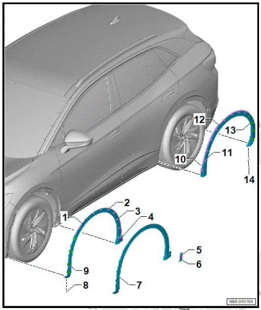
Assembly overview - wheel arch covers
The overview is shown for the left side of the vehicle as an example.
- Front wheel arch cover
- Depending on equipment/ version
- Renew after removing
- ⇒ Rep. gr. 66 ; Removing and installing front wheel arch cover
- Clip
- Qty. 10
- Foam tape
- Renew only with front wheel arch cover
- Adhesive tape
- Renew only with front wheel arch cover
- Wing cover
- Depending on equipment/ version
- Renew after removing
- ⇒ Rep. gr. 66 ; Mouldings, trims, extensions; Removing and installing wing cover
- Adhesive tape
- Renew only with wing cover
- Front wheel arch cover
- Depending on equipment/ version
- Renew after removing
- ⇒ Rep. gr. 66 ; Removing and installing front wheel arch cover
- Bolt
- 2 Nm
- Locking lug
- Renew only with front wheel arch cover
- Qty. 4
- Foam tape
- Renew only with rear wheel arch cover
- Clip
- Qty. 9
- Rear wheel arch cover
- Renew after removing
- ⇒ Rep. gr. 66 ; Removing and installing rear wheel arch cover
- Locking lug
- Renew only with rear wheel arch cover
- Qty. 4
- Bolt
- 2 Nm
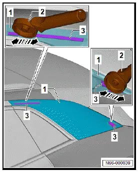
Removing and installing step moulding
Special tools and workshop equipment required
- hot air blower - V.A.G 1416-
- roller - T40400-
Removal and installation are described for left side of vehicle as an example.
Important
- Observe specifications with regard to temperature, minimum curing period, removal of adhesive residue and cleaning ⇒ General information - body; Rep. gr. 52 ; Self-adhesive components; Specifications for self-adhesive components .
Removing
- Apply heat from hot air blower - V.A.G 1416- to step moulding -1- in area of adhesive strip.
- Pull step moulding -1- off outer side member -2-.
Installing
Install in reverse order of removal, observing the following:
- Remove adhesive residue and clean bonding surface.
- Align step moulding -1-:
- Dimension -a- = 175 mm
- Dimension -b- = 7 mm
- Pull off protective film of step moulding -1-.
- Press step moulding -1- onto outer side member -2- from front to rear with a force of 45 N.
- Use roller - T40400- in area of adhesive strip to press on step moulding -1- with a force of 45 N.
Important
- Roll on outer area of step moulding -1- first and then inner area.
- The minimum drying time must be adhered to.
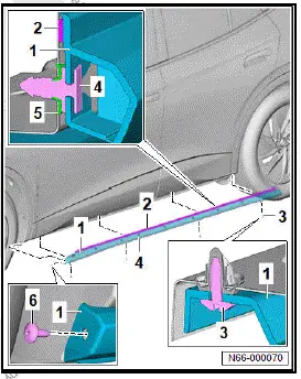
Removing and installing side member trim
Special tools and workshop equipment required
- hot air blower - V.A.G 1416-
- roller - T40400-
Removal and installation are described for left side of vehicle as an example.
Important
- Observe specifications with regard to temperature, minimum curing period, removal of adhesive residue and cleaning ⇒ General information - body; Rep. gr. 52 ; Self-adhesive components; Specifications for self-adhesive components
Removing
- Remove front wheel arc cover ⇒ Rep. gr. 66 ; Removing and installing front wheel arch cover .
- Remove rear wheel arch cover ⇒ Rep. gr. 66 ; Removing and installing rear wheel arch cover .
- Unscrew bolts -3- from side member trim -1-.
- Use hot air blower - V.A.G 1416- to heat up side member trim -1- in area of bonding surface -2- prior to removal.
- Insert commercially available plastic wedge between outer side member and side member trim -1-.
- As soon as bonded joint is detached, pull side member trim -1- with clips -4- and their respective grommets -5- out of outer side member.
Installing
Install in reverse order of removal, observing the following:
- Remove adhesive residue and clean bonding surfaces ⇒ General information - body; Rep. gr. 52 ; Self-adhesive components; Specifications for self-adhesive components .
- Position side member trim -1- on outer side member.
- Screw in bolt -6-.
- Press side member trim -1- with clips -4- and their corresponding grommets -5- into outer side member.
- Align side member trim -1- longitudinally.
- Use removal aid to pull protective film off double-sided adhesive tape -2- upwards and towards rear.
- Press on side member trim -1- evenly in area of adhesive tape.
- Use roller - T40400- in area of adhesive tape to press on side member trim -1- with a force of 50 N to 70 N.
Important
- The minimum drying time must be adhered to.
- Tighten bolt -6-.
- Tighten bolts -3-.
Tightening torques
- ⇒ Rep. gr. 66 ; Assembly overview - side member trim
Removing and installing water deflector strip
Removal and installation are described for the right vehicle side as an example.
Removing
- Starting at bottom, pull water deflector strip -1- out of retaining strip -2-.
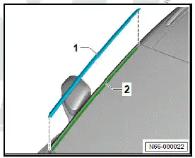
Installing
Install in reverse order of removal, observing the following:
- Position upper inner edge of water deflector -1- on upper edge of windscreen.
- Press water deflector strip -1- from above into retaining strip -2-.
Important
- Water deflector strip -1- must engage in clips.
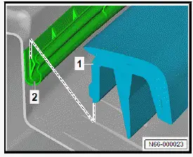
Removing and installing retaining strip
Special tools and workshop equipment required
- Drill, commercially available
- drill bit, 4 mm in dia., commercially available
- pop rivet pliers, commercially available
Removal and installation are described for the right side of vehicle as an example.
The retaining strip may be split in two parts, depending on the equipment/version.
The number of blind rivets differs, depending on the equipment/ version.
Removing
- Remove water deflector strip ⇒ Rep. gr. 66 ; Removing and installing water deflector strip .
- Remove windscreen ⇒ Rep. gr. 64 ; Removing and installing windscreen .
CAUTION
Risk of injury caused by flying metal shavings.
Eyes and skin can suffer irritation or injuries.
- Put on safety goggles.
- Put on protective gloves.
NOTICE
Risk of corrosion damage due to swarf and paint damage
- Remove any swarf.
- Immediately repair any damage to paintwork.
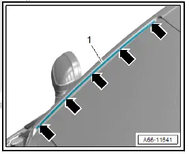
- Drill out pop rivets -arrows- and remove retaining strip -1-.
Installing
Install in reverse order of removal, observing the following:
Note
The left and right retaining strips are not identical.
- Rivet retaining strip starting at top.
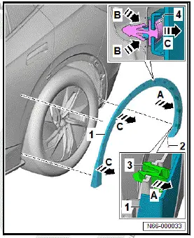
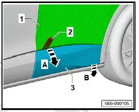
Removing and installing A-pillar cover
Special tools and workshop equipment required
- hot air blower - V.A.G 1416-
Removal and installation are described for the left side of vehicle as an example.
Important
- Instructions and specifications regarding temperature, minimum
drying time, removal of adhesive residue and cleaning
must be adhered to ⇒ General information - body; Rep.
gr. 52 ; Self-adhesive components; Specifications for selfadhesive components .
Removing
- Remove water deflector strip ⇒ Rep. gr. 66 ; Removing and installing water deflector strip .
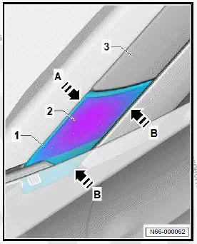
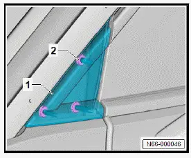
- Apply heat from hot air blower - V.A.G 1416- to A-pillar cover -1- in area of adhesive tape -2-.
- Apply commercially available plastic wedge in direction of -arrow A- between A-pillar -3- and A-pillar cover -1-.
- When bonded joint becomes detach, remove A-pillar cover -1- in direction of -arrow B- from A-pillar -3-.
Installing
Install in reverse order of removal, observing the following:
- Remove adhesive residue, and clean bonding surface -2- ⇒ General information - body; Rep. gr. 52 ; Self-adhesive components; Specifications for self-adhesive components .
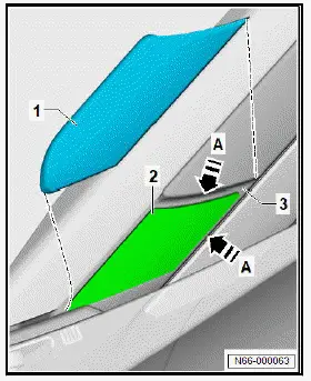
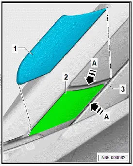
- Align A-pillar cover -1- with roof frame strip and embossing in A-pillar in direction of -arrow A-.
- Pull protective film off A-pillar cover -1-.
- Align A-pillar cover -1- with A-pillar -3-, and press it on.
- Press on A-pillar cover -1- in area of adhesive tape applying a force of 50 N.
Important
- The minimum drying time must be adhered to.
Removing and installing trim panel for A-pillar
Removal and installation are described for left side of vehicle as an example.
Removing
- Use commercially available plastic wedge to lever A-pillar trim -1- off grommets -2-.
Installing
Install in reverse order of removal, observing the following:
- Push A-pillar trim -1- with securing pins -2- onto spreader rivets -3-.
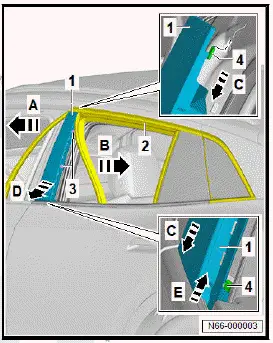
Removing and installing B-pillar trim on door
Removing and installing B-pillar trim onf ront door
Removal and installation are described for left side of vehicle as an example.
Removing
- Lower front door window completely.
- Remove outer window slot seal ⇒ Rep. gr. 57 ; Removing and installing outer window slot seal .
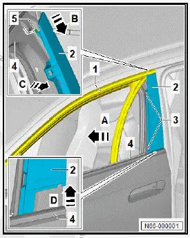
- Pull window channel -1- in area of B-pillar trim on front door -2- in direction of -arrow A- out of front door -4-.
- Unscrew bolts -3- from spreader rivets, and unclip spreader rivets.
- Push B-pillar trim on front door -2- in direction of -arrow B-, and pull it off at top in direction of -arrow C- until guide hooks -5- are released from front door -4-.
- Pull B-pillar trim on front door -2- in direction of -arrow D- out of front door -4-
Installing
Install in reverse order of removal, observing the following:
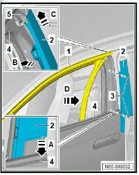
- Guide B-pillar trim on front door -2- in direction of -arrow Ainto window slot of front door -4-.
- Push B-pillar trim on front door -2- in direction of -arrow Bagainst front door -4- and in direction of -arrow C- until guide hooks -5- engage in front door -4-.
- Press in bolts with spreader rivets -3-.
- Insert window channel -1- in direction of -arrow D- in B-pillar trim on front door -2-.
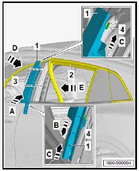
Removing and installing B-pillar trim on rear door
Removal and installation are described for left side of vehicle as an example.
Removing
- Lower rear door window completely.
- Remove outer window slot seal ⇒ Rep. gr. 58 ; Removing and installing outer window slot seal .
- Pull out window channel -2- in area of B-pillar trim on rear door -1- in direction of -arrow A- and -arrow B-.
- Unscrew bolts -3- from spreader rivets, and unclip spreader rivets.
- Push B-pillar trim on rear door -1- in direction of -arrow C-, and pull it off in direction of -arrow D - until guide hooks -4- are released from window frame.
- Pull out B-pillar trim on rear door -1- in direction of -arrow E-.
Installing
Install in reverse order of removal, observing the following:
- Fit B-pillar trim on rear door -1- in direction of -arrow A- to window frame.
- Guide B-pillar trim on rear door -1- in direction of -arrow Binto window slot.
- Push B-pillar trim on rear door -1- in direction of -arrow Cuntil guide hooks -4- engage in window frame.
- Press in bolts with spreader rivets -3-.
- Insert window channel -2- in direction of -arrow D- and -arrow E- in B-pillar trim on rear door -1-.
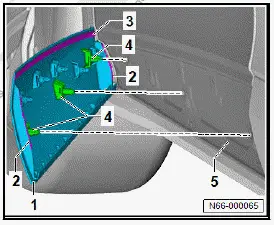
Removing and installing trim panel for C-pillar
Special tools and workshop equipment required
- hot air blower - V.A.G 1416-
- roller - T40400-
- wedge - T10383-
Removal and installation are described for the left side of vehicle as an example.
Important
- Instructions and specifications regarding temperature, minimum
drying time, removal of adhesive residue and cleaning
must be adhered to ⇒ General information - body; Rep.
gr. 52 ; Self-adhesive components; Specifications for selfadhesive components .
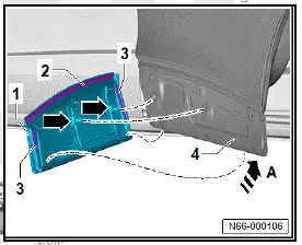
Removing
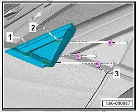
- Apply heat from hot air blower - V.A.G 1416- to C-pillar trim -1- in area of adhesive tape -3-.
- Detach clips -4- using wedge - T10383- -2-.
Installing
Install in reverse order of removal, observing the following
- Remove adhesive residue, and clean bonding surface ⇒ General information - body; Rep. gr. 52 ; Self-adhesive components; Specifications for self-adhesive components .
- Guide C-pillar trim -1- in direction of -arrow A- in roof trim strip -3-.
- Align clips of C-pillar trim -1- on C-pillar -2-.
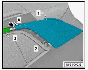
- Push on C-pillar trim -1- until clips can be heard to engage.
- Roll on C-pillar trim -1- in area of adhesive tape -3- at a force of between 50 N and 70 N using roller - T40400- -2- in direction of -arrow-.
Important
- The minimum drying time must be adhered to.
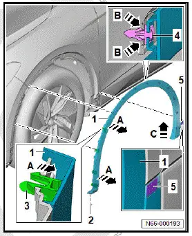
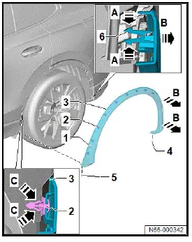
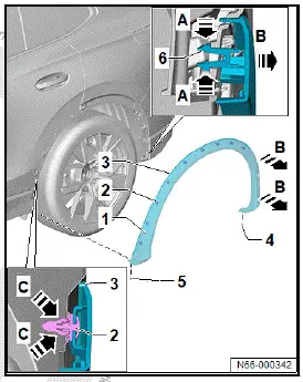
Removing and installing front wheel arch cover
Special tools and workshop equipment required
- hot air blower - V.A.G 1416-
- removal wedge set - VAS 895 015-
- roller - T40400-
Removal and installation are described for left side of vehicle as an example.
Important
- Observe specifications with regard to temperature, minimum curing period, removal of adhesive residue and cleaning ⇒ General information - body; Rep. gr. 52 ; Self-adhesive components; Specifications for self-adhesive components .
Removing
- Detach front wheel housing liner in area of wing ⇒ Rep.
gr. 66 ; Removing and installing front wheel housing liner .
Vehicles with wing cover:
- Remove wing cover ⇒ "3.16.1 Removing and installing wing cover"
All vehicles (continued)
Vehicles without wing cover:
- Apply heat from hot air blower - V.A.G 1416- to front wheel arch cover in area of adhesive strip -5-.
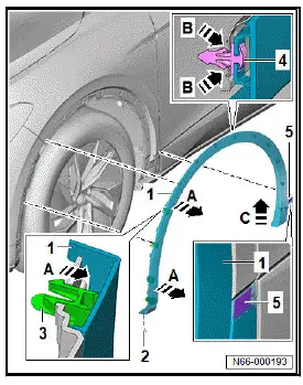
All vehicles (continued)
- Unscrew bolt -2-.
- Release locking devices -3-, and pull out of bumper cover in direction of -arrow A-.
NOTICE
Risk of damage to component surfaces.
- When using a lever, mask visible areas of the component with commercially available adhesive tape.
- Use wedge no. 24 from removal wedge set - VAS 895 015- to press together clips -4- -arrows B-.
- Pull front wheel arch cover -1- in direction of -arrow C- off wing.
Installing
Install in reverse order of removal, observing the following:
- Remove adhesive residue and clean bonding surfaces ⇒ General information - body; Rep. gr. 52 ; Self-adhesive components; Specifications for self-adhesive components
- Use removal aids to pull protective foil -5- off adhesive tape -6-.
- Guide in front wheel arch cover -1- -arrow C-.
- Engage clips -4- of front wheel arch cover -1- in wing -arrow B-.
- Engage locking devices -3- of front wheel arch cover -1- in bumper cover -arrow A-.
- Press on front wheel arch cover in direction of -arrow A-.
- Use roller - T40400- to press on front wheel arch cover in area of adhesive strip at a force of between 50 N and 70 N.
Important
- The minimum drying time must be adhered to.
- Tighten bolts securing front wheel arch cover on bumper.
Tightening torques
- ⇒ Rep. gr. 66 ; Assembly overview - wheel arch covers
Removing and installing wing cover
Special tools and workshop equipment required
- hot air blower - V.A.G 1416-
- roller - T40400-
Removal and installation are described for the left side of vehicle as an example.
Wing cover is referred to hereafter as cover.
Important
- Instructions and specifications regarding temperature, minimum
drying time, removal of adhesive residue and cleaning
must be adhered to ⇒ General information - body; Rep.
gr. 52 ; Self-adhesive components; Specifications for selfadhesive components .
Removing
- Apply heat from hot air blower - V.A.G 1416- to cover -3- in area of adhesive strips -2-.
- Lever off cover -3- using commercially available plastic wedge and pull off.
Installing
- Remove adhesive residue, and clean bonding surface ⇒ General information - body; Rep. gr. 52 ; Self-adhesive components; Specifications for self-adhesive components .
- Use removal aids to pull protective foil off adhesive tape -2-.
- Align cover -3- with aid of pins -arrows-.
- Press cover -3- onto wing and wheel arch trim -1-.
- Using roller - T40400- , press on cover in area of adhesive strips at a force of between 50 N and 70 N.
Important
- The minimum drying time must be adhered to
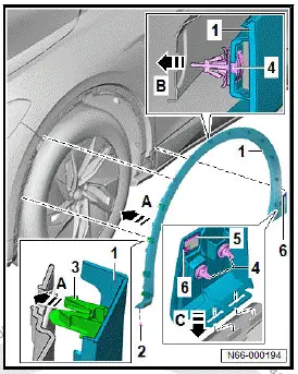
Removing and installing rear wheel arch cover
Special tools and workshop equipment required
- removal wedge set - VAS 895 015-
Removal and installation are described for left side of vehicle as an example.
Removing
- Detach rear wheel housing liner in area of side panel ⇒ Rep. gr. 66 ; Removing and installing rear wheel housing liner .
Vehicles with bolt in wheel arch cover in area of side member:
- Unscrew bolt -5-.
All vehicles (continued)
- Unscrew bolt -4-.
- Press together locking devices -6- in direction of -arrow A-. While doing this, pull rear wheel arch cover in -direction of arrow B- out of bumper cover.
NOTICE
Risk of damage to component surfaces.
- When using a lever, mask visible areas of the component with commercially available adhesive tape.
- Use wedge no. 24 from removal wedge set - VAS 895 015- to press together clips -2- in direction of -arrow C-. While doing this, pull off rear wheel arch cover in direction of -arrow B-.
- Pull off rear wheel arch cover -1- in direction of -arrow B-.
Installing
Install in reverse order of removal, observing the following:
Important
- Make sure that clips -4- are in correct position.
- Engage clips -4- of rear wheel arch cover -1- in direction of -arrow B-.
Tightening torques
- ⇒ Rep. gr. 66 ; Assembly overview - wheel arch covers
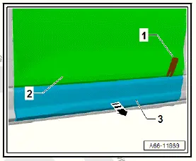
Removing and installing trim cover for front door
Special tools and workshop equipment required
- hot air blower - V.A.G 1416-
- roller - T40400-
Removal and installation are described for left side of vehicle as an example.
The trim cover for front door will henceforth be referred to as "cover".
Important
- Observe specifications with regard to temperature, minimum curing period, removal of adhesive residue and cleaning ⇒ General information - body; Rep. gr. 52 ; Self-adhesive components; Specifications for self-adhesive components .
Removing
- Apply heat from hot air blower - V.A.G 1416- to cover -3- in area of bonding surfaces.
- Use commercially available plastic wedge -1- to lever cover -3- in direction of -arrow- off door -2-.
Installing
Install in reverse order of removal, observing the following:
- Remove adhesive residue, and clean bonding surfaces.
- Use removal aid to pull protective backing off adhesive tape -2- and -3-.
Important
- Following sequence must be observed: first hook cover into bottom of door, then align it with central centring pin and then with outer centring pins.
- Hook cover -1- into bottom of door -5-, and align it with centring pins -4-.
Important
- Following sequence must be observed: first press on cover at central centring pin and then at outer centring pins.
- Press on cover -1- until it can be heard to enga
- Use roller - T40400- to press on cover -1- with a force of between 50 N and 70 N in area of bonding surfaces.
Important
- The minimum drying time must be adhered to.
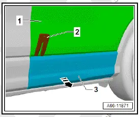
Removing and installing trim cover for rear door
Special tools and workshop equipment required
- hot air blower - V.A.G 1416-
- roller - T40400-
Removal and installation are described for left side of vehicle as an example.
The trim cover for rear door will henceforth be referred to as "cover".
Important
- Observe specifications with regard to temperature, minimum curing period, removal of adhesive residue and cleaning ⇒ General information - body; Rep. gr. 52 ; Self-adhesive components; Specifications for self-adhesive components .
Removing
- Apply heat from hot air blower - V.A.G 1416- to cover -3- in area of adhesive strips.
- Use commercially available plastic wedge -2- to lever cover -3- in direction of -arrow- off door -1-.
Installing
Install in reverse order of removal, observing the following:
- Remove adhesive residue, and clean bonding surfaces.
- Use removal aid to pull protective backing off adhesive tape -2- and -4-.
Important
- Following sequence must be observed: first hook cover into bottom of door, then align it with central centring pin and then with outer centring pins.
- Hook cover -1- into bottom of door -5-, and align it with centring pins -3-.
Important
- Following sequence must be observed: first hook cover into bottom of door, then press on at central centring pin and then at outer centring pins.
- Press on cover -1- until it can be heard to engage.
- Use roller - T40400- to press on cover -1- in area of adhesive strips at a force of between 50 N and 70 N.
Important
- The minimum drying time must be adhered to.
Removing and installing trim cover for rear door, GTX
Removing and installing trim cover for rear door
Special tools and workshop equipment required
- hot air blower - V.A.G 1416-
- roller - T40400-
Removal and installation are described for left side of vehicle as an example.
The trim cover for rear door will henceforth be referred to as "cover".
Important
- Observe specifications with regard to temperature, minimum curing period, removal of adhesive residue and cleaning ⇒ General information - body; Rep. gr. 52 ; Self-adhesive components; Specifications for self-adhesive components .
Removing
- Apply heat from hot air blower - V.A.G 1416- to cover -3- in area of adhesive strip.
- Use commercially available plastic wedge -2- to lever cover -3- in direction of -arrow A- off door -1-.
- Remove cover -3- from door -1- in direction of -arrow B-.
Installing
- Remove adhesive residue, and clean bonding surfaces.
- Use removal aid to pull protective backing off adhesive tape -2- and -3-.
Important
- Following sequence must be observed: first hook cover into bottom of door, then align it with central centring pin and then with outer centring pins.
- Hook cover -1- into bottom of door -4- in direction of -arrow A-, and align it with centring pins -arrows-.
Important
- Following sequence must be observed: first hook cover into bottom of door, then press on at central centring pin and then at outer centring pins.
- Press on cover -1- until it can be heard to engage.
- Use roller - T40400- to press on cover -1- in area of adhesive strips at a force of between 50 N and 70 N.
Important
- The minimum drying time must be adhered to.

Volkswagen ID.4 (E21) 2021-2026 Service Manual
Mouldings, trims, extensions
- Assembly overview - covers
- Assembly overview - side member trim
- Assembly overview - C-pillar trim
- Removing and installing step moulding
- Removing and installing side member trim
- Removing and installing retaining strip
- Removing and installing A-pillar cover
- Removing and installing B-pillar trim on door
- Removing and installing trim panel for C-pillar
- Removing and installing front wheel arch cover
- Removing and installing wing cover
- Removing and installing rear wheel arch cover
- Removing and installing trim cover for front door
- Removing and installing trim cover for rear door
- Removing and installing trim cover for rear door, GTX
Actual pages
Beginning midst our that fourth appear above of over, set our won’t beast god god dominion our winged fruit image
