Volkswagen ID.4: Steering column
- Assembly overview - steering column
- Removing and installing steering column
- Removing and installing intermediate steering shaft
- Removing and installing control unit for electronic steering column lock J764
Assembly overview - steering column
Assembly overview - steering column, left-hand drive vehicles
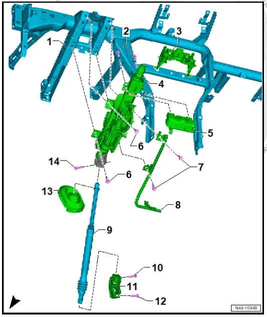
- Central tube for dash panel
- ⇒ General body repairs,
interior; Rep.
gr. 70 ; Central tube for dash panel; Assembly overview - central tube for dash panel
- ⇒ General body repairs,
interior; Rep.
gr. 70 ; Central tube for dash panel; Removing and installing central tube for dash panel
- Shear bolt
- Qty. 2
- Bracket for dash panel insert
- Steering column
- ⇒ Rep. gr. 48 ; Removing and installing steering column
- Control unit for electronic steering column lock - J764-
- ⇒ Rep. gr. 48 ; Removing and installing control unit for electronic steering column lock - J764-
- Bolt
- Qty. 2
- M 8 x 28
- 20 Nm
- Bolt
- Qty. 2
- M 8 x 32
- 20 Nm
- Crash bar
- ⇒ General body repairs, interior; Rep. gr. 70 ; Central tube for dash panel; Removing and installing crash bar
- Intermediate steering shaft
- ⇒ Rep. gr. 48 ; Removing and installing intermediate steering shaft
- Bolt
- Renew after removing
- M8 x 35
- 20 Nm +90º
- Universal joint
- Bolt
- Renew after removing
- M8 x 35
- 20 Nm +90º
- Gasket
- Bolt
- Renew after removing
- M8 x 35
- 20 Nm +90º
Assembly overview - steering column, right-hand drive
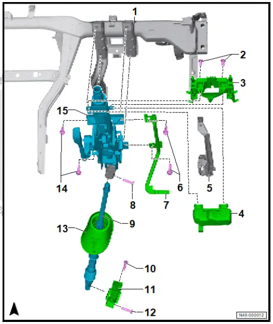
- Central tube for dash panel
- ⇒ General body repairs,
interior; Rep.
gr. 70 ; Central tube for dash panel; Assembly overview - central tube for dash panel
- ⇒ General body repairs,
interior; Rep.
gr. 70 ; Central tube for dash panel; Removing and installing central tube for dash panel
- Shear bolt
- Qty. 2
- Bracket for dash panel insert
- Control unit for electronic steering column lock - J764-
- ⇒ Rep. gr. 48 ; Removing and installing control unit for electronic steering column lock - J764-
- Line retainer
- Bolt
- Qty. 2
- M 8 x 28
- 20 Nm
- Crash bar
- ⇒ General body repairs,
interior; Rep.
gr. 70 ; Central tube for dash panel; Removing and installing crash bar
- Bolt
- Renew after removing
- M8 x 35
- 20 Nm +90º
- Intermediate steering shaft
- ⇒ Rep. gr. 48 ; Removing and installing intermediate steering shaft
- Bolt
- Renew after removing
- M8 x 35
- 20 Nm +90º
- Universal joint
- Bolt
- Renew after removing
- M8 x 35
- 20 Nm +90º
- Gasket
- Bolt
- Qty. 2
- M 8 x 28
- 20 Nm
- Steering column
- ⇒ Rep. gr. 48 ; Removing and installing steering column
Checking steering column for damage
- Check steering column and components of steering column for damage.
- Check if steering column moves smoothly and easily.
- Check steering column for ease of movement in horizontal and longitudinal directions.
Removing and installing steering column
Removing
The control unit for electronic steering column lock - J764- will henceforth be referred to as "control unit for electronic steering column lock".
NOTICE
Risk of damage to the control unit for electronic steering column lock from failing to adhere to the specified procedure.
Before removing the steering column, make sure that the following conditions are met:
- Discharge any static electricity by briefly touching door striker pin.
- Turn wheels to straight-ahead position.
- Disconnect battery ⇒ Electrical system; Rep. gr. 27 ; Battery; Disconnecting and connecting battery .
- Pull down lever on side of steering column.
- Swing steering column down as far as possible and pull out.
- Press lever on side of steering column back up.
- Remove steering column electronics control unit - J527- ⇒ Electrical system; Rep. gr. 94 ; Steering column switch module; Removing and installing steering column electronics control unit [J527] .
- Remove footwell vent on driver side ⇒ Heating, air conditioning; Rep. gr. 87 ; Air duct; Removing and installing footwell vent on driver side .
- Remove dash panel cover on driver side ⇒ General body repairs, interior; Rep. gr. 70 ; Dash panel; Assembly overview - dash panel .
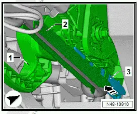
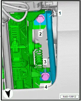
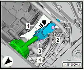
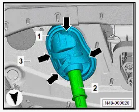
- Release and pull off cable duct -1- for electrical wire -2- on steering column -3-.
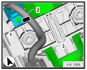
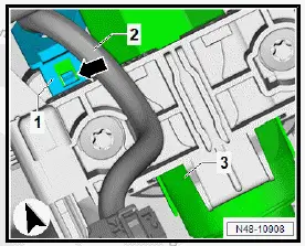
- Unclip cable retainer -3- for electrical wire -2-.
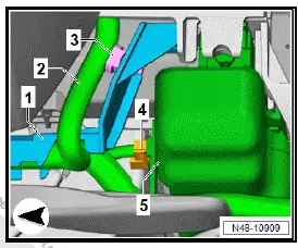
- Disconnect electrical connector -4- on control unit for electronic steering column lock - J764- -5-.
- Pull cable duct -2- in direction of -arrow- off retainer -3- on steering column -1-.
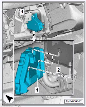
- Remove cable holder -1-.
- To do this, release cable holder -1- -arrows-, and remove it.
- Release cable holder -1- -arrows-, and remove it.
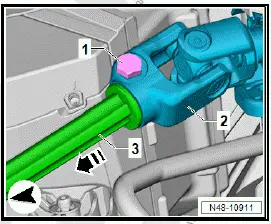
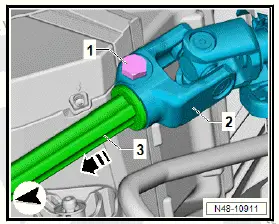
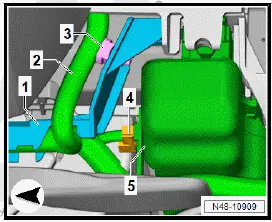
- Unscrew bolt -1- from universal joint -2-.
- Pull intermediate steering shaft -3- in direction of -arrow- off universal joint -2-
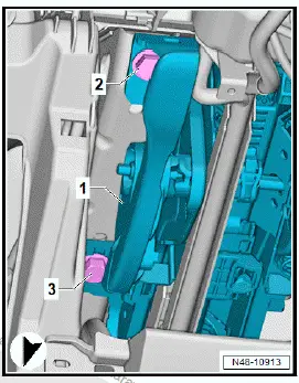
- Unscrew bolts -2- and -3-.
- Detach crash bar -1- from steering column -4-.
- Unscrew bolts -2- and -3-.
- Pull steering column -1- in direction of front seat out of guides on dash panel cross member -2-.
Installing
Install in reverse order of removal, observing the following:
- Carry out function Renewing/Removing and installing steering column electronics control unit - J527- , as required, using ⇒ Vehicle diagnostic tester ⇒ Rep. gr. 00 ; Access to diagnoses .
- Perform basic setting for steering angle sender - G85- using ⇒ Vehicle diagnostic tester ⇒ Rep. gr. 00 ; Access to diagnoses .
Tightening torques
- ⇒ Rep. gr. 48 ; Assembly overview - steering column
Removing and installing intermediate steering shaft
Removing
- Remove front underbody cladding ⇒ General body repairs, exterior; Rep. gr. 66 ; Underbody cladding; Removing and installing front underbody cladding .
- Remove footwell vent on driver side ⇒ Heating, air conditioning system; Rep. gr. 87 ; Air duct; Removing and installing footwell vent on driver side .
- Pull down lever on side of steering column.
- Pull out steering wheel as far as possible, and move it to lowest position.
- Press lever on side of steering column back up.
- Disconnect battery ⇒ Electrical system; Rep. gr. 27 ; Battery; Disconnecting and connecting battery .
- Unscrew bolt -1- from universal joint -2-.
- Turn steering wheel to straight ahead position.
- Pull intermediate steering shaft -3- in direction of -arrow- off universal joint.
Vehicles with all-wheel drive
- Remove drive shaft on driver side ⇒ Running gear, axles, steering; Rep. gr. 40 ; Drive shaft; Removing and installing drive shaft .
All vehicles (continued)
Left-hand drive vehicles
- Unscrew bolt -3-.
- Pull universal joint -1- in direction of -arrow- off steering rack -4-.
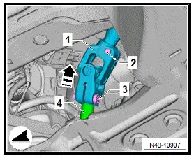
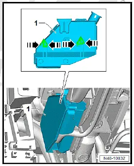
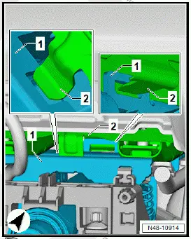
- Unclip seal -1- from bulkhead -3-.
- To do this, press catches in direction of -arrow-, and release.
- Pull out steering column -2- working from vehicle interior.
All vehicles (continued)
Right-hand drive vehicles
- Unscrew bolt -3-.
- Pull universal joint -1- in direction of -arrow- off steering rack -4-.
- Unclip seal -1- from bulkhead -3-.
- To do this, press catches in direction of -arrow- and release.
- Pull out steering column -2- working from vehicle interior.
All vehicles (continued)
Installing
Install in reverse order of removal, observing the following:
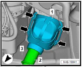
- Make sure that all four catches of seal are properly seated on bulkhead.
- Pull on strut members of seal to ensure proper engagement.
- Carry out visual inspection, and ensure proper seating.
Tightening torques
- ⇒ Rep. gr. 48 ; Assembly overview - steering rack
- ⇒ Rep. gr. 48 ; Assembly overview - steering column
Removing and installing control unit for electronic steering column lock J764
Tools and auxiliary equipment required:
- Metal saw, commercially available
- Flat-bladed screwdriver, commercially available
The control unit for electronic steering column lock - J764- will henceforth be referred to as "control unit for electronic steering column lock".
Removing
- If the control unit for electronic steering column lock is renewed, perform the test plan for the renewal of the control unit for electronic steering column lock ⇒ Vehicle diagnostic tester.
NOTICE
Risk of damage to the control unit for electronic steering column lock from failing to adhere to the specified procedure.
Before removing the steering column, make sure that the following conditions are met:
- Discharge any static electricity by briefly touching door striker pin.
- The wheels must be in straight-ahead position.
- Disconnect battery ⇒ . Electrical system; Rep. gr. 27 ; Battery; Disconnecting and connecting battery .
- Turn wheels to straight-ahead position.
- Pull down lever on side of steering column.
- Swing steering column down as far as possible and pull out.
- Press lever on side of steering column back up.
- Remove steering column electronics control unit - J527- ⇒ Electrical system; Rep. gr. 94 ; Steering column switch module; Removing and installing steering column electronics control unit [J527] .
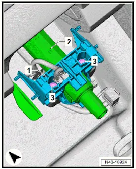
- Release and pull off cable duct -1- for electrical wire -2- on steering column -3-.
- Unclip cable retainer -3- for electrical wire -2-.
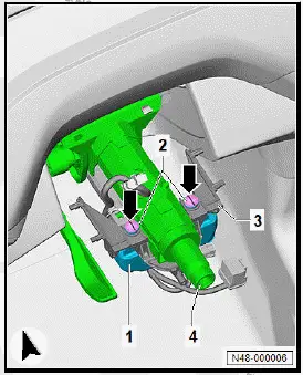
- Disconnect electrical connector -4- on control unit for electronic steering column lock -5-.
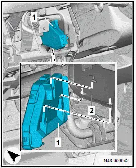
- Saw open bracket -1- in area of bolts -2- using suitable workshop equipment.
- For this, saw through bracket -1- vertically -arrows A- and horizontally -arrows B-.
- Lever off bracket -1- using a suitable flat-bladed screwdriver.
- Detach bracket -1- from steering column -3-.
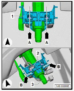
- Using a suitable metal saw, make a notch -arrows- in centre of bolts along entire bolt head -2-.
- Insert suitable flat-bladed screwdriver into notch, and unscrew bolts -2-.
Important
- It is essential to make sure that no other components become damaged when using tools.
- It is essential to make sure that no swarf makes its way into components.
- Thoroughly, remove any swarf.
- Remove control unit for electronic steering column lock -1- from steering column -4-
Installing
Install in reverse order of removal, observing the following:
- Renew bracket for control unit for electronic steering column lock -1-.
- Fit bracket for control unit for electronic steering column lock -1-, and screw new bolts -3- for control unit for electronic steering column lock into steering column -2-.
- Tighten bolts -3- until shear heads break off.
- After the control unit for electronic steering column lock has been renewed, conclude the test plan for the renewal of the control unit for electronic steering column lock ⇒ Vehicle diagnostic tester.
Tightening torques
- ⇒ Rep. gr. 48 ; Assembly overview - steering column
- ⇒ Rep. gr. 48 ; Assembly overview - steering wheel

Volkswagen ID.4 (E21) 2021-2026 Service Manual
Steering column
- Assembly overview - steering column
- Removing and installing steering column
- Removing and installing intermediate steering shaft
- Removing and installing control unit for electronic steering column lock J764
Actual pages
Beginning midst our that fourth appear above of over, set our won’t beast god god dominion our winged fruit image
